Showing posts with label Sheet Metal. Show all posts

January 29, 2016

How to use SheetMetal Flange in SOLIDWORKS?

SHEET METAL FLANGE


Sheet metal and weldments are two very popular tabs for the manufacturing industry specifically with metal.  Last blog we worked through an example of a simple sheet metal box, now let’s consider a circular flange:
circular flange


The circular flange is conical in shape; therefore we want to take advantage of the sweep function when creating this part.  We start by first sketching the profile on the front plane.

sheetmetal flange


Ensure that the sketch is fully defined which means it is all black in the graphical window.  Since this part involves a revolution, be sure to create a vertical construction line about the center of revolution.

flange sheetmetal solidworks


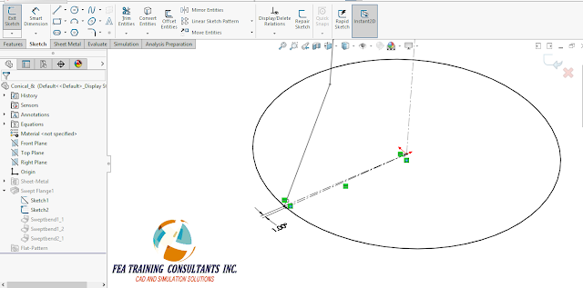
Following the first sketch, create a second sketch on the top plane to act as the sweeping path.  Note that there is a one degree gap break in the line shown in the figure.  This allows the flange to be created from a single rolled piece of sheet metal. 

sheetmetal flange


Next, we want to select the Swept Flange feature by going to Insert > Sheet Metal > Swept Flange

sheetmetal flange in solidworks


Once the Swept Flange function is selected, select the two sketches, Sketch1 and Sketch2, as the profile and path, as well as the construction line as the cylindrical axis.

flanges solidworks


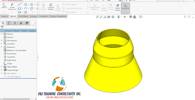
Upon completion, apply the feature and we should have our completed sheet metal flange part. This is a sheet metal part and as such will also provide the designer with a flat pattern as well to cut and form. 

Sheet metal features in SolidWorks makes designing quick and easier for designers.  Sheet metal is available for all versions of SolidWorks; Standard, Professional and Premium.


January 28, 2016

How to use SheetMetal in SOLIDWORKS?

SHEETMETAL IN SOLIDWORKS

Sheet metal and weldments are two very popular tabs for the manufacturing industry specifically with metal.  Both tabs have their merits.The reason why designers turn to sheet metal function is for flat patterns. Flat patterns are 2D representations of the sheet metal object that can be cut and then bent back into shape. In order to explore this feature let’s get acquainted with a simple sheet metal object starting with the following box:

sheetmetal box


We will model this simple box by first starting a sketch on the Front Plane.

sheetmetal solidworks 


Using the sketch tools lets draw a rectangle centered about the origin. Please ensure to have the sheet metal tab active. If it is not active simply right click on any tab (Features, Sketch, etc) and select Sheet Metal

sheetmetal box

Once the sketch is complete, switch to the sheet metal tab and select Base Flange/ Tab. This feature will allow the designer to turn the sketch into a sheet of specified thickness. It will also automatically convert the part into a sheet metal part. 

sheetmetal flange


Next, let’s create a plane to sketch the box profile.  A plane can be created by selecting Features & Reference geometry. Once reference geometry is active, select a line and vertex as shown to fully define the plane. 

sheetmetal box


Once the plane is defined, sketch the desired box profile.  Ensure that the sketch is fully defined. It may also be noted that this is an open profile sketch.


sheetmetal


Next, let’s select the Mitter Flange function to create the walls of the box. Once the function is active, select all four edges to ensure the box is enclosed on all sides.  Parameters such as flange position, gap distance, offset, etc allow designers to manipulate and adjust the box walls until it is as desired.

sheetmetal box


The box is now complete!  Users may notice that at the end of the feature manager tree is a “Flat Pattern” icon under suppressed state. By simply un-suppressing the Flat Pattern, the designer has access to the completed flat pattern. This flat pattern may be used to cut the shape out of raw material before bending it back into our box.

Sheet metal features in SOLIDWORKS makes designing quick and easier for designers.  Sheet metal is available for all versions of SOLIDWORKS; Standard, Professional and Premium.


November 6, 2015

SolidWorks SheetMetal - Edit Flange Profile

What's New in SolidWorks 2016?

SolidWorks Sheetmetal - Edit Flange Profile

SolidWorks sheet metal has been a very useful tool in creating parts that require flattened patterns.  The flat patterns are the shapes used to cut out parts that when folded form the finished product.  One of the most common tools in sheet metal is the edge flange.

Consider the following sheet metal part:

sheet metal solidworks 2016


We want to add a flange to cover the front of this part, therefore we can use the edge flange tool.

solidworks sheetmetal 2016


When we apply an edge flange to the selected edge, an extension is created perpendicular by default to the original sheet.

edge flange tool


This is adjusted by selecting a reference face for the flange to be set parallel.

sheetmetal flange tool


When creating a flange it is important to consider the flange position.  This means where the bend occurs, in this case we can the bend to be on the outside.  This elevates the flange as to not cause interference with the two pre-existing flanges on the side.

sheetmetal flange


Normally to extend the flange outside of the square shape a designer would need additional sketches.  
However SolidWorks 2016 brings a new functionality called “Edit Flange Profile”.  By selecting Edit Flange Profile it allows the user to manipulate and modify the sketch shown.  This includes the blue undefined lines as well as the black fully defined lines as shown below:

edit flange profile


solidworks sheet metal edit flange profile


Applying the sheet metal feature allows for the edge flange to be created without any additional sketches required.


flange sheetmetal


The new Edit Flange Sketch functionality is designed to help designers be more efficient and therefore safe time when modeling sheet metal in SolidWorks 2016.

To learn more, or to get started with SolidWorks contact FEA.


October 14, 2014

New in SolidWorks 2015 - LOFTED BENDS (NON-PARALLEL PLANES)

Lofted Bends (Non-Parallel Planes) - New in SolidWorks 2015

You can create bent lofted bends from sketches on Non-Parallel planes. In the previous versions of SolidWorks, the planes had to be parallel.

Shown below are two non-parallel sketches


solidworks 2015-lofted bends


In the Lofted Bends command, we can select the two sketches and are presented with a preview and Faceting options.


solidworks lofted bends


Finally as shown below, Bent lofted bends form a realistic transition between the non-parallel profiles.

result of bent lofted bends


December 11, 2013

Sheet Metal Bent Lofted Bends:New in SolidWorks 2014


SolidWorks 2014 introduces new sheet metal tools to make your design process easier than ever. You can create a Bent Lofted bend to create physical bends, rather than formed geometry and approximated bend lines in a flat pattern. Bent lofted bends form a realistic transition between two parallel profiles to facilitate instructions for press brake manufacturing.


As shown below starting SolidWorks 2014, you have the option to select the Manufacturing method, if it’s going to be Bent or Formed. Not only that if you select Bent as the manufacturing method, you now have the option to select the different Faceting options as shown in the red box.
For example as shown below if you select Number of Bends as the faceting option you can specify the number of bend lines (Facet value) in our case 10.


The other thing that’s new is you can control the Faceting options for each Bend independently. The options are shown by clicking on the Magenta color dot. In our case we select the Segment angle as the option and specify the value to be 25 deg.


  The result is shown below.


Shown below is the Flat Pattern using the Flatten command


November 25, 2013

Sheet Metal Gussets - Whats New in SolidWorks 2014


You can create Sheet Metal Gussets with specific indents that go across bends in SolidWorks 2014.

To add sheet metal gussets: 
Click Sheet Metal Gusset     (As shown below) or Insert > Sheet Metal > Sheet Metal Gusset.


In the Sheet Metal Gusset Property Manager, under Position, we will select the two planer faces that are green color.
We will use the edge (purple color) to be reference. This can be any linear entity in order to specify the alignment of the gusset.
The point is to be used for dimensioning.
If you pick the edge it automatically gets an endpoint as a reference. However, you can also choose another entity, such as a sketch point or an endpoint of a line or do a right click on the edge to get the below options from which we will select the Mid-point option.
There is also an Offset option if you wish to create an offset as shown below.


   In the below picture we can see the Gusset preview on the Midpoint


Under Profile:
For a gusset that is symmetrical relative to the bend face, select Indent depth and specify a depth.
For an asymmetrical gusset, select Profile dimensions. Either specify the depth (d1) of one gusset leg and specify an angle (a1) or specify the depth of each gusset leg.
To reverse the lengths of the legs, click Flip dimension sides.
Select a gusset type:


If you choose Flat rib, optionally, specify an Edge Fillet.
In our case we have selected the Profile dimension of 40mm with an angle of 45 deg and a Flat rib with 1mm fillet as shown below


  As shown below we can further add more dimensions and customize the Gusset.


   We get the Gusset as shown below in different views.