Showing posts with label solidworks assembly. Show all posts

November 3, 2023

Catch Up on the Best of SOLIDWORKS

Discover hundreds of parts, assemblies, drawings, and user experience enhancements added to the last five SOLIDWORKS releases

Each year SOLIDWORKS introduces significant enhancements focused on improving your daily design productivity. With so much to learn each year, it’s understandable to miss a feature or two.

Not to worry, the below videos have you covered with the best parts, assemblies, drawings, and user experience enhancements included in the last FIVE SOLIDWORKS releases.

SolidWorks Parts 2020-2024

Parts Catch-Up: 2020-2024

Check out part modeling features and workflows, including Stud Wizard, 3D Texture, and Color Picker


SolidWorks Drawings 2024

Drawings Catch-Up: 2020-2024

See new drawing workflows and capabilities, including BOM Filters, GTOL interface, and Detailing Mode


SOLIDWORKS Assemblies 2024

Assemblies Catch-Up: 2020-2024


View new assembly workflows and increased performance, including Atomic STEP, Magnetic Mates, Faster Open, and Graphic Times


solidworks 2024 user experience

User Experience Catch-Up: 2020-2024

Explore enhancements to everyday user experience, including S-Key Command Search, Hide/Show reference geometry, and Comments


Learning about new features is just the beginning. Contact us to take your design skills to the next level.

September 5, 2015

Exploded Views in SOLIDWORKS

Exploded Views

An exploded view is a useful tool to show how parts fit inside an assembly.  It can be used as a marketing tool to promote the product or it can also be used during manufacturing to show how the product is physically assembled.  Both tasks can be achieved with a video animation or a drawing representation.  

Consider a flashlight assembly as shown below:

solidworks exploded view


This flashlight is composed of many different component parts.  Exploded views are treated as an assembly configuration, therefore to create an exploded view we need to go to the configuration tab.

exploded view configration


The current configuration active is named “Explode” but it does not necessary have to be named as such.  Right click the current configuration and select “New Exploded View”.  

exploded view config


Once the Explode property menu is active you may now select individual or multiple parts to explode with each step.  You have the ability to manually move and/or rotate the part an arbitrary distance or move the part a specific distance using the explode step properties.  In this case the first part exploded is the Locking Pin

creating exploded views


Creating multiple steps will allow you to explode the entire assembly to highlight each component piece.  Please note that you may apply more than one step to a single component should you want to.


exploded views solidworks


Once the assembly is fully exploded, under the configurations tab you may right click the exploded view configuration to select “Collapse” or “Animate Collapse”.  Animate collapse will animate the process and in doing so you will have the option to save the video for later use.  Similarly once an assembly is collapsed, you may “Explode” or “Animate Explode”.

animate explode in exploded view


August 18, 2015

Large Assemblies? No sweat!!

Large Assemblies

Projects can vary in size from small to large.  On occasion, the larger projects may demand larger models in order to capture the full scope of the project.  With increasingly complex models and intricate parts with many features it will invariably have an impact on your computer performance.  It is worth noting that there are simple tricks you can use to improve performance for large assemblies.

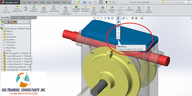
Change the display to Shaded or Wireframe

This is one of the simplest and easiest methods, simply drop down the view bar options and select either shaded or wireframe.  This can give a boost to performance.

large assembly solidworks


Set it to lightweight

When a component is set to fully resolved, all of the model data is loaded into memory.  When it is set to lightweight, only some of the model data is loaded into memory, the rest is loaded as required.  This applies to both parts and assemblies.  Consider the following gearbox assembly:

improve performance of large assembly solidworks


Right click on a component, in this case a part was chosen, and select component properties.

component properties large assembly solidworks


The component property box will appear where you can navigate to Suppression State and select Lightweight


large assemblies solidworks


In doing so the components will be set to lightweight, furthermore as a visual cue, SolidWorks modifies the part icon to include a feather to indicate that it is lightweight.

large assembly solidworks


Activate Large Assembly Mode

Large assembly mode is an optimized set of system settings that will improve performance for larger assemblies.  Upon opening an assembly a dialogue box will open when SolidWorks determines that the component is a large assembly (i.e. a threshold has been reached).  You may choose to accept large assembly mode by accepting the dialogue box.  Or you may manually turn on large assembly mode by going to tools > Large assembly mode 

large assembly mode


May 30, 2015

Modeling in Assembly

ASSEMBLY MODELING 


Conventional modeling practices allow users to create a part and combine multiple parts in an assembly.  It is worth knowing that this is not the only approach to modeling. You have the option to model straight from assembly mode.

Consider a new assembly:

solidworks assembly


From this new assembly select Insert > Component > New Part.  A new generic part file will be created in the feature manager design tree:

solidworks part in an assembly


Select your part, right click and select “Edit Part”


edit part in solidworks assembly


In this example let’s sketch a simple rectangle on the top plane

sketching part in solidworrks assembly


Extrude the rectangle to create a solid.  Please note that we are still in Assembly mode, However, we are working under the “Edit Component” feature.

modeling in assembly solidworks


Similarly we can insert a new part and sketch on a rectangle on the right plane as shown.  Please note that the collinear relation was used to define the rectangle.

solidworks assembly


Extrude to create your second part

assembly solidworks


We can repeat the process to insert a new part and sketch on the front plane as shown below to make the third part

solidworks modeling assembly


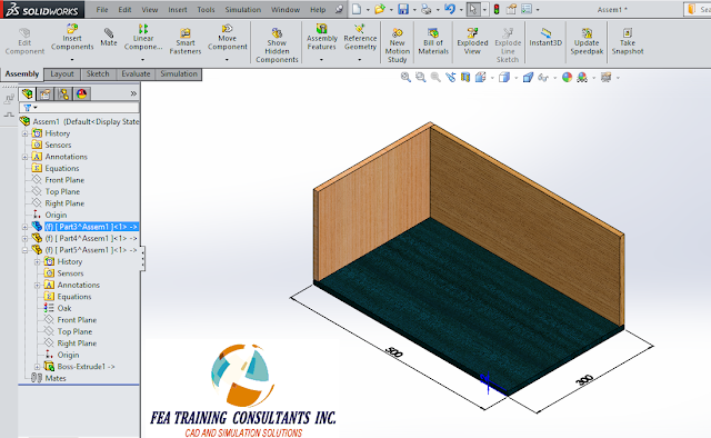
With all three parts complete, you may apply your materials to the parts, in this case various woods were selected. 

solidworks modeling


Remember to save your new assembly with the new parts created from the assembly.  In the saving process you will encounter this message indicating that you will need to save the parts that were created.  Select save externally in order to have the part files created. 

solidworks assembly


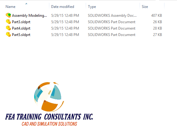
Finally, you will find your part files created in the same file location as the assembly.

solidworks assembly


May 26, 2015

Rigid and Flexible Assemblies

When creating parts in your design you will most likely create assemblies as well.  An assembly is a group of parts held together by mates.  Consider the assembly mechanism below.  The mates are created such that the top handle is able to rotate, thus transmitting the motion from one yoke to another. 


rigid and flexible assembly solidworks


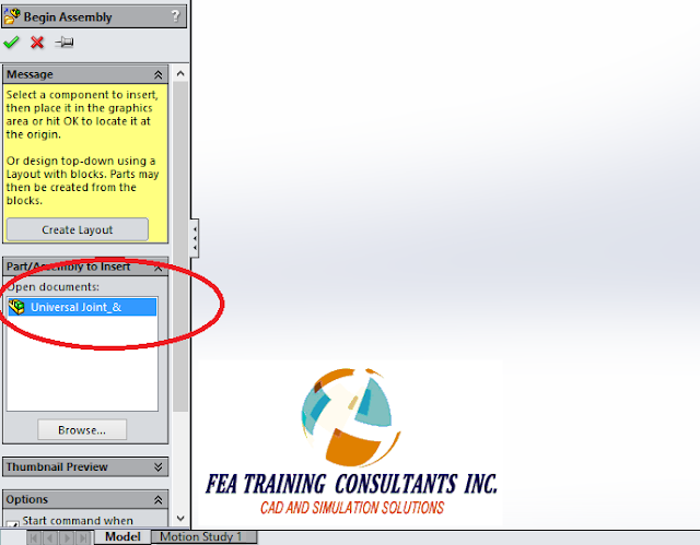
We may create subassemblies by placing one premade assembly into another.  In this case we are placing the universal joint mechanism as shown above into a new assembly

solidworks assembly


Once the universal joint mechanism assembly is placed into a new assembly, you will find that the entire mechanism is rigid and unable to move despite having no restriction for movement.


assembly mechanism solidworks


By default, when an assembly is placed into another assembly it is treated as rigid.  To change this we can right click the subassembly and select Properties


rigid assembly solidworks


When the component properties box opens navigate to the Solve as section and select Flexible.  Accept.


flexible assembly solidworks


With that change implemented you will find that the subassembly mechanism is now freely available to rotate.