
Discover valuable SOLIDWORKS technical tips, informative videos, and exclusive promotions on the FEA Training Consultants blog. As an authorized SOLIDWORKS Reseller Canada, we offer expert insights and support to help you maximize your design capabilities. Stay informed on the latest SOLIDWORKS features and access to special offers to enhance your engineering solutions.
Showing posts with label solidworks simulation professional. Show all posts
Showing posts with label solidworks simulation professional. Show all posts
August 18, 2015

July 31, 2015
Contact Sets in SOLIDWORKS SIMULATION
Simulation Contact Set
SolidWorksSimulation of assemblies or multi bodies requires the application of contact
sets to define the interface between two objects. If the contact sets are not defined properly
we will obtain incorrect results.
Consider a simple weldment framed structure
with a steel plate sitting on top.

This
weldment is fixed at the end of each leg and has a load applied to the plate on
top.

By default,
SolidWorks Simulation treats weldments as beam elements and the plate on top as
a solid element. As such we have two
different element types in this analysis; therefore we need to define a contact
set. As an option we can use the
“automatically find contact set” function by selecting a beam element and the
plate. The software will find the
connecting surface where you may apply a condition, in this case bonded. This is repeated for all four faces.

Upon closer
inspection, we find those contact sets to be a face to face contact

Following
the creation of the contact sets we can mesh our model and run the analysis


However in
doing so will result in an error message.
This is
because the contact set defined was incorrect.
When the contact sets were created they were treated as faces, however
since this is a solid to a beam element, we need to select the beam element
contact set under “Type”. By redefining
all four contact sets, remeshing and running the study, we now have the correct
results.

June 29, 2015
Application of Loads in SolidWorks Simulation
Simulation: Application of Loads
SolidWorks Simulation allows users to set up
and run tests using finite element analysis (FEA).
The manner in which a user sets up a test will determine whether the
results are an accurate result of real-world conditions. (Also Read:Symmetry in SolidWorks Simulation -Guide to applying loads and restraints appropriately)
Consider
the electrical component shown below.
The main grey surface consists of ceramic porcelain whereas the small
red parts indicate components that generate heat on the board. We are interested in the heat distribution
for this part under working conditions.

In order to
set up the problem we define the material properties for each component. This includes the red electrical components
as well as the grey ceramic porcelain.
Following material definition, we define heat generation power of 0.2W
for the red components and convection of 0.2 W/m^2 K for the outside
surfaces. The convection is a mechanism
of heat transfer used to dissipate the heat.
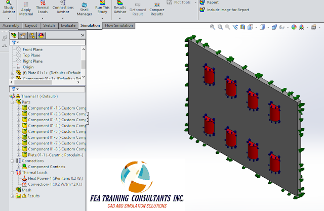
It is
important to pay attention to detail when defining a simulation study. Consider the definition of 0.2W heat
generation for the red components. The
user must differentiate whether the heat generation is generated for each
component or whether it is generated across the sum total of components. This is an important distinguishing
factor. In this case it is set to “Per
item” which is correct.
Furthermore,
as a tip, if the user were to use symmetry to divide a heat generating part in
half and the heat generation is defined in terms of Watts, it follows that the
Watt value must also be divided by half since Watt is a total heat generating
value. The relationship is similar to
that of force and pressure.

Once the
analysis is successfully set up we need to mesh the component.

Once the
component is meshed, we may run the analysis.
According to the conditions set for this thermal analysis we are seeing
a maximum value of 460C occurring on the inner components. The heat generated from the components
travels outward to a temperature of 427C towards the outer edges of the ceramic
porcelain.

The manner
in which the simulation analysis was set up can greatly affect the
results.


June 19, 2015
Bolt Fracture
Case Study: Bolt Fracture
Hardware
such as bolts, nuts and washers are generally used for connections and
fixtures. They form an integral part of
the component structural integrity.
Bolts are governed by standards such as ASTM and are typically stamped
with an identifying marking on the head during the manufacturing process. The bolts selected for any application
typically take into account the manner in which it is applied while taking into
account the most prevalent mode of failure.
It follows that it would be in the designer’s best interest to
understand how bolts fail and to avoid those situations.
Consider a
simple bolt modeled in SolidWorks:
Roundhead
Bolt 12mm DIA x 152MM LONG ASTM A307

It is worth
noting that the tensile strength for that grade of bolt is approximately 60,000
PSI. Therefore, using plain carbon steel
as a template, the tensile strength was adjusted accordingly.

Next, we can
set up a test scenario using SolidWorks Simulation where the bolt is fixed at
the top with a base tensile load of 10,000 PSI applied at the bottom

We can now
mesh the bolt

After
running the Static analysis we can do a section plot to understand how the
stress a distributed in the cross section of the bolt. We find that the highest point of stress concentration
occurs at the neck as expected with a value of 28,067 PSI.

Note
that this value is fairly close to yield strength of the material 31,994
PSI. If a stress value approaches the
yield strength, the general assumption of linear behavior of the material
begins to breakdown. Therefore it is in
our best interest to run a non-linear analysis as well.
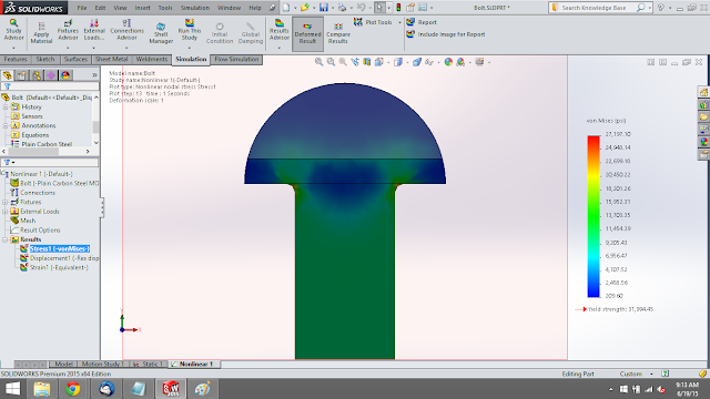
Creating a
new non-linear study and running a similar analysis we find that the actual
stress is approximately 27,197 PSI. This value is less than the linear analysis
but it is still close to yield.


May 20, 2015
Difference between Direct Transfer and Rigid Connection
In SolidWorks Simulation you may define external
loads known as remote loads. Upon
creation of a remote load you have the option of setting it to be either Direct
Transfer or Rigid Connection. What is
the difference?
Consider a
simply supported cantilever composed of two parts: front and back:

We may
create a simulation study that reflects the cantilever beam loading
conditions. It is fixed on one end and
has a load applied on the other end.

We can
simulate the results of this study by excluding half of the beam and applying a
remote load in place.

When
creating a remote load, the user must specify whether it is a direct transfer
or rigid connection

Direct Transfer: Assumes that the component between
the remote force and the connection point is adequately flexible, allowing the structure to deflect. The program decomposes the remote force into
a shear force and coupling moment acting on the connection face. This allows the connection face to distort. Displacements must be within the small
displacement assumption.

Rigid Connection:
Applies rigid links/ connections from the remote load to the connecting
face. As a result when the face deflects,
the face shape is maintained. High
stresses can develop near faces with rigid connections.

The results
of the remote load direct transfer is shown below:

The results
of the remote load rigid connection are shown below:

At first
glance the results are not easily distinguishable; however upon closer
inspection along the vertical axis of the connection face reveals that the
stress distribution from the direct transfer and rigid connection options are
different.


Choosing
whether the remote load will be applied as a direct transfer or rigid
connection will affect the simulation results.
Subscribe to:
Posts (Atom)