Showing posts with label solidworks features. Show all posts

January 29, 2016

Weldment Cut List in SOLIDWORKS

WELDMENT CUT LIST


Last blog we explored the creation of a simple weldment frame.  A natural extension to the weldment features is the cut list which lists all the parts and lengths required to make the weldment.  It is very similar in nature to a bill of material.  Consider our weldment frame:
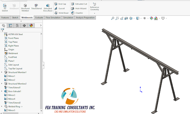
weldment solidworks


We’ll start by creating a drawing for this weldment by first going to File> Make Drawing from Part.

weldment cut list


A simple drawing is created with a plan, elevation, side and isometric view.  Now we would like to insert our cut list.

cut list


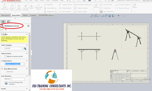
In order to insert a cut list go to Annotation> Tables > Weldment Cut List

SOLIDWORKS WELDMENTS


cut list weldment


In the Weldment Cut List Property box, the designer is able to change and modify various parameters such as the table name/ template, position, etc.


weldment cut list


Once a table has been completed, the designer will find a list of sections including description, quantity, length and item number.  You might notice that there are special entries such as plate and Weld-On Ring.  The Weld-On Ring is a special unique part therefore has a separate entry, however the plate was the base plate we modeled.  The cut list conveniently lists the dimensions of the plate.  These dimensions are controlled by a bounding box.

weldment solidworks


If the designer needs to make changes or even edit the bounding box, it is done simply by going back to the model, expand the cut list and right click the part of your choice and select Edit Bounding Box.  This is a very useful feature to capture items such as base plates, stiffeners and gussets, all very common structural elements.

Weldment features in SolidWorks makes designing quick and easier for designers.  Weldment is available for all versions of SolidWorks; Standard, Professional and Premium.


September 5, 2015

Exploded Views in SOLIDWORKS

Exploded Views

An exploded view is a useful tool to show how parts fit inside an assembly.  It can be used as a marketing tool to promote the product or it can also be used during manufacturing to show how the product is physically assembled.  Both tasks can be achieved with a video animation or a drawing representation.  

Consider a flashlight assembly as shown below:

solidworks exploded view


This flashlight is composed of many different component parts.  Exploded views are treated as an assembly configuration, therefore to create an exploded view we need to go to the configuration tab.

exploded view configration


The current configuration active is named “Explode” but it does not necessary have to be named as such.  Right click the current configuration and select “New Exploded View”.  

exploded view config


Once the Explode property menu is active you may now select individual or multiple parts to explode with each step.  You have the ability to manually move and/or rotate the part an arbitrary distance or move the part a specific distance using the explode step properties.  In this case the first part exploded is the Locking Pin

creating exploded views


Creating multiple steps will allow you to explode the entire assembly to highlight each component piece.  Please note that you may apply more than one step to a single component should you want to.


exploded views solidworks


Once the assembly is fully exploded, under the configurations tab you may right click the exploded view configuration to select “Collapse” or “Animate Collapse”.  Animate collapse will animate the process and in doing so you will have the option to save the video for later use.  Similarly once an assembly is collapsed, you may “Explode” or “Animate Explode”.

animate explode in exploded view


August 21, 2015

Methods to create threads in SolidWorks

Creating Threads: Sweep Method

The SolidWorks toolbox has many useful premade configurable models for hardware items such as hex nuts, bolts and washers.  This helps quicken modeling time by avoiding the need to model smaller simpler items.  However creating specific features such as threads may be considered challenging to some.  The following will outline the sweep method in creating thread.
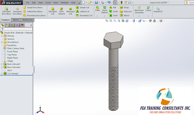
Consider a simple modeled hex bolt without threads

THREADS IN SOLIDWORKS sweep method


 To apply threads, we must first create the cut profile.  Please note the cut profile is very specific to each thread and bolt therefore it is suggested to consult reference information for accurate modeling.

creating threads solidworks sweep method


Next we need to create a spiral using the Helix/ Spiral tool in SolidWorks.  This is where you can set the number of revolutions, pitch etc.


sweep method


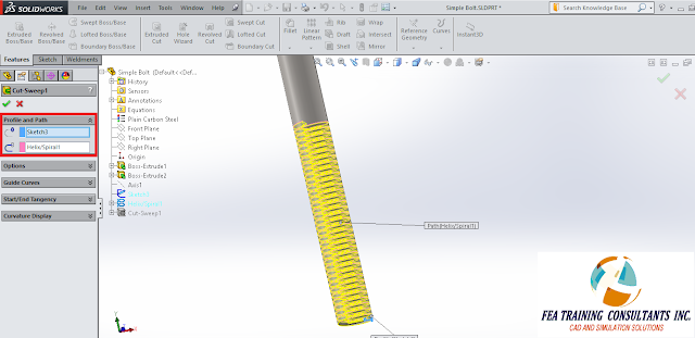
Next, apply the Sweep Cut feature by selecting the cut sketch profile followed by the spiral that was created.  By applying this feature the threads will appear on the hex bolt

sweep cut feature solidworks


This represents one method to create threads on bolts.  In practise many times it is not necessary to go into such high detail since bolts are purchased stock to specifications.  However on the occasion that a high fidelity model is required such as for marketing or rendered images, this would be considered one method to apply threads to a part.

sweep method threads solidworks


August 17, 2015

Applying Decals in SolidWorks

Using Decals

Solid Modeling has many stages and uses that include concept, design and final product.  Some solid models are used to convey information to a client or sometimes it is provided for marketing purposes.  In either case it is valuable to have a high fidelity model and sometimes that includes the application of Decals onto a solid body.  

Consider the following bracket:

solidworks decal


In order to add a decal, expand the task menu and select Appearances, Scenes and Decals on the right hand side.  Browse through the decals an select the one you want.  In this case the SolidWorks decal will be applied.  Right click and select Add decal to part

decal in solidworks


The Decal property box will appear there it will provide a preview of the decal

decals solidworks


Select a face on the part to apply the decal. 

decals solidworks


  You’ll notice there is a triad available as well as resizing point around the perimeter of the decal.  This allows you to reposition and resize the decal to the proper size.  Once you as satisfied, select apply.

decals solidworks


This decal has been successfully applied.  However you may notice that the background color does not match the part color.  In order to make them match, a mask needs to be applied.
Select and applying a new decal for reference.
decals in solidworks


Scrolling down the decal property box you will find the Mask Image option.  Select “Selective Color Mask” and click on the eye dropper icon.  With the eye dropper icon selected, select the color which you would like to omit from the decal. i.e. make it transparent.  In this case white is chosen.

\decal solidworks


As a result the new decal has a mask successfully applied.  The inclusion of the mask makes the decal and model look cleaner.

July 28, 2015

How to use "Curve through XYZ Points"?

Curve through xyz points

Data can be provided to the designer in a variety of ways from contract drawings, field measurement, word of mouth etc.  In the case of field measurement or established geometries, the data can come in the form of a plotted coordinate system. 

Let us consider the profile of an airfoil.  The geometrical features of an airfoil effect the flow and thus performance of the airfoil in operation.  It is important to model the geometry as accurately as possible.  The geometry is given in the form of an x-y coordinate system.  

xy coordinates


It is worth noting that an additional column was added with all zeros in order to represent the dimensions for the Z plane.  The three column as given in excel format is not as useful, therefore we can copy the data by selecting the columns and selecting copy and paste it in a text document.

curve through xyz points


imported curve solidworks


Save the text document since you will need to select it soon.

 Next we can start a new part in SolidWorks.  In order to bring the airfoil into SolidWorks you can sketch individual points and draw a spline connecting all the points.  This manual method is repetitive, labor intensive and time consuming.  A more efficient method would be to use the “Curve through XYZ Points” tool from the feature tab.

curve through xyz points


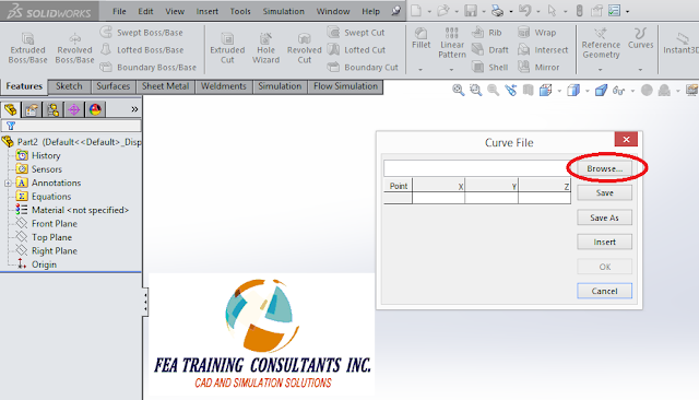
After selecting “Curve through XYZ Points”, click on browse and select the text file with the coordinates that was created.

xyz points solidworks


  Upon selection you should see the points and data values populating the X, Y and Z coordinates.  Select “OK”.

curve through xyz points


  Now you should have a full accurate curved geometry that was constrained by the X,Y and Z coordinates that were imported.  Creating this curve using this method is significantly quicker than manually plotting each point and connecting them with a spline.  “Curve through XYZ Points” is one of many features that makes solid modeling faster and more efficient in SolidWorks.