Showing posts with label meshing. Show all posts

October 20, 2015

New in SolidWorks Simulation 2016 - Ability to section the mesh

New in SOLIDWORKS  Simulation 2016

  SolidWorks Simulation is a great tool to test your part in a virtual environment to understand how it behaves under loading conditions.  Consider the following simple hook:

sw simulation 2016


We are going to run a simple simulation study on this hook to determine how it behaves.  The hook is fixed at the eyelet at the top and it is experiencing a 1000 N force downward. 

whats new in solidworks simulation 2016


By running the finite element analysis we get our results

fea 2016 solidworks


We see that the hook is experiencing a maximum stress of 12Mpa at the expected location.  As part of the simulation process, the software ‘meshes’ the part by breaking it into small elements to prepare it for analysis.

meshing in solidworks simulation 2016


  New to SolidWorks Simulation 2016 is the ability to section the mesh.  This may be done before or after the analysis, as long as the part is meshed, you can section it.


meshin in solidworks simulation 2016


Sectioning will show all the elements intersecting the plane of choice.  This ability ensures that you have the desired mesh density at any location in your model.  Areas of high stress concentration will require higher mesh density for accurate results.  Using mesh sectioning you can now see how the mesh is distributing throughout the entire model.  


September 30, 2014

SolidWorks Simulation:Meshing of failed Parts

If you have part(s) that fail to mesh in an assembly model, the part icon in the Simulation Parts list will be indicated by a red hashed icon, as shown in the image below.  But with the latest releases of SOLIDWORKS Simulation (2011 and above), you can fix this issue by right-clicking the part and choosing to Create Mesh for that part alone. 


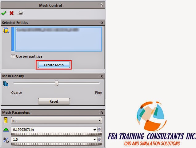
This selection will take you into the Mesh Control dialog, see image below, where you can adjust settings for the mesh size if you want, but simply clicking the Create Mesh button here will re-mesh only that part but still in the context of the assembly.


You are reminded of this fact by a pop-up telling you what is happening, see image below.  (1) It creates a mesh control in the tree, and regardless of the mesher previously used, it will mesh the failed part using the Curvature based mesher. 
(2) It will also automatically create Contact Sets using faces that are touching neighboring parts.  Most likely the reason why the part failed to mesh in the first place was that the differences in part sizes prevented it from maintaining a compatible mesh.  If there was interference between parts, another reason for parts failing to mesh, then you need to manually define the Contact Set to appropriately define their interaction


When all parts have successfully meshed, the top level Part icon will have a check indicating that everything is meshed, see image below.