Showing posts with label solidworks surfacing. Show all posts

January 7, 2016

SOLIDWORKS Flat Patterns

FLAT PATTERNS


Flat patterns of complex geometries can be difficult to produce whether they be for sheet metal parts or even plastic parts.  Industries have different requirements and SOLIDWORKS 2016 has tools to help the designer achieve their goals. 

 Consider the following plastic cover:

flat pattern in solidworks


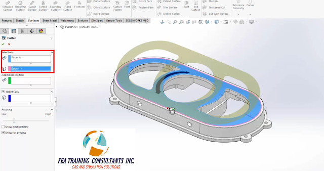
To create a flat pattern of the top curved, complex surface we simply use the flatten feature from the surfaces tab and select the faces and edges required.

flat pattern solidworks


In doing so, we have a flattened version of the surface shown in the component preview.  In SOLIDWORKS 2016 designers can now flatten any surface, including ones that contain holes.  In this example that mean the arrow marks.


flat pattern


By selecting perimeter of the 3D curved arrow and adding it to the Additional Entities property box, it is now included and formed onto the flattened pattern

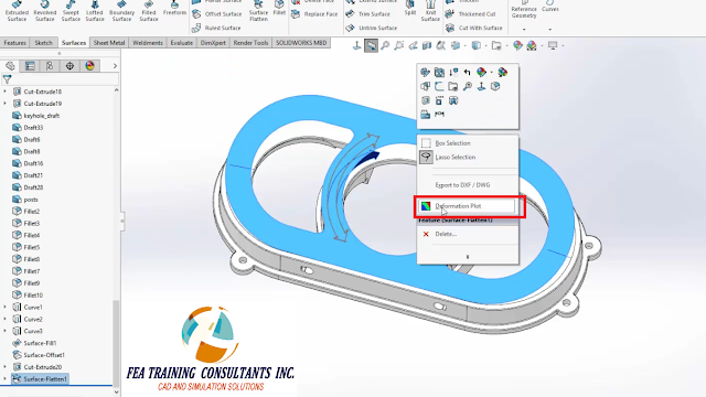
In designing flat patterns stresses are induced when forming the shape.  To see the stretch and deformation the designer can simply right click the flat pattern and select deformation plot.

flat pattern stress


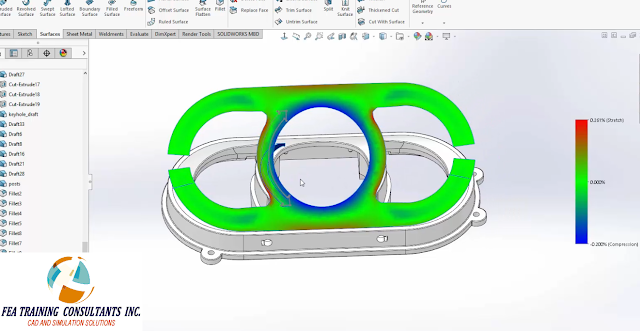
The deformation plot shows the areas of stretch and compression from the forming process. 

flat pattern deformation plot


In order to alleviate these stresses we can introduce relief cuts, a new function to SOLIDWORKS 2016.  


FLAT PATTERN RELEIF CUTS


By selecting the cut line entities, the software will can update with a new flattened pattern.


FLAT PATTERN SOLIDWORKS 2016


Now when we check the stretch and compression plot as a result of forming, we find that the part is subjected to far less stress.

SOLIDWORKS 2016 delivers new and improved tools to help designers make flat patterns easier and quicker than before.


July 8, 2015

Surfacing Tool in SOLIDWORKS

Simple Surface

Basic geometric shapes such as cubes and cylinders are easily defined however; 3D CAD software can do much more.  When a designer takes advantage of the 3D software capabilities, more complex shapes may be created and defined. 
  Consider a complex feature such as a compound curve.  Compound curves may be defined in SolidWorks using the surfacing tool.  In order to define this curve it must be constrained using three sketches.  The image below contains a sketched curve on the Front, Right and Top Plane.  Please note that the curve is sketched in a solid line whereas parts that do not define the curve are kept as construction lines.

solidworks surfacing


Each curve may be modified to suit your chosen geometry.  The numerical values in this example are arbitrary however note that each curve shares a termination point from start to finish.

solidworks surface tool


Next, activate the surfaces tab and select the boundary surface tool.  This tool creates a surface within the bounded conditions.  In this case the bounded conditions will be the sketches.  Under Direction 1 tab, select the two sketches on the Right and Front Plane.

solidworks surface tool


Please note that the curve as shown is incomplete since the surface is only bound by the two sketches as reflected in the preview.  The bottom edge of the surface needs to follow the contour as outlined on the Top plane sketch.  To do so, activate Direction 2 and select the top plane sketch.

surface tool solidworks


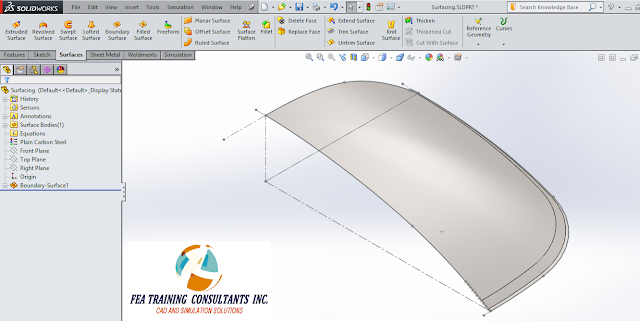
Now the compound curve is properly bound by all three sketches.  We may now accept and apply this feature

surface tool


A fully defined compound curve surface is now defined.  This surface may now be used to complete a part or work as a simplified model for an FEA analysis.  The tools to create 3D parts such as compound curves are all available in SolidWorks.