Showing posts with label solidworks 2013. Show all posts

March 3, 2014

Smart Mates - SolidWorks 2013 vs SolidWorks 2014

 
SMART MATES
The SmartMates functionality saves time by allowing you to create commonly-used mates without using the Mate PropertyManager.
To use the SmartMates command in SolidWorks 2013 and older version of SolidWorks, you can access it from Move Component on the Assembly toolbar. In the PropertyManager, under Move, click SmartMates as shown below

 
To do the mates you need to double-click a component and then click a valid mate partner. As shown below when you double-click the first component it becomes transparent indicating Smart Mate.
Now we select the other mating component and the Mate pop-up toolbar appears as shown below.
 
 
We can do the same procedure for the other mate. Double click the first component and then select the other mating component.
 
The mate toolbar pops up as shown below.
 
You can include the SmartMates command when customizing the Assembly toolbar or the Assembly CommandManager as shown below.
To include the SmartMates command in the CommandManager:
1. Open an assembly.
2. Click Tools > Customize, or right-click the CommandManager and select Customize.
3. On the Commands tab, select Assembly.
4. Drag the SmartMates command to the Assembly CommandManager, and click OK.


June 12, 2013

Converting Drawing View to Sketch (SolidWorks 2013 Feature)


Have you ever wanted to take a drawing view and make it into a standard block that you could use in layout drawings? You have a part model, but you only want a 2D “picture” of it? You want to mirror a drawing view, avoiding to create the model for the opposite hand part, since the only thing needed is an extra Isometric view

The answer to above questions is this new feature in 2013 version of SolidWorks. This feature enables you to convert a drawing view to sketch entities or a block of sketch entities using the Convert View to Sketch PropertyManager.

The other advantage of this is if you convert you views to sketch, you can directly send the drawing file to other users, no need to send the part or assembly model.

convert drawing view in solidworks


From the shortcut menu, you can convert a drawing view to sketch entities or a block of sketch entities.

In a drawing view, right-click and click Convert View to Sketch as shown in the picture below.


In the Convert View to Sketch Property Manager, you can get the following three options as shown in the picture below. Here we are selecting the first option that is Replace view with sketch.

 
Replace view with sketch: Replaces the drawing view with equivalent 2D sketch entities.
Replace view with block: Replaces the drawing view with equivalent 2D sketch entities that are grouped in a block.
Insert as block: Creates a separate block comprised of equivalent 2D sketch entities that you can place anywhere in the drawing.
You need to do this for each view individually. Once done you will hardly see any difference between the drawing view and the one replaced with sketch as shown below. The advantage is now you can forward this drawing file to any user and he should be able to open this without the need of 3D model.
 
 
The difference is in the Property Manger is as shown below. You will see that there are very few options shown when you select a view.


April 11, 2013

Varying Dimension Pattern (SolidWorks 2013 Feature)


The Instance to Vary option in the Linear and Circular Pattern Property Managers allows you to vary the dimensions and locations of instances in a feature pattern. You can vary the dimensions of a series of instances, so that each instance is larger or smaller than the previous one. You can also change the dimensions of a single instance in a pattern and change the position of that instance relative to the seed feature of the pattern.

For linear patterns, you can change the spacing between the columns and rows in the pattern. For circular patterns, you can arrange the instances to become closer together or farther apart.

Below is a part with the slot cut into it. We will pattern that slot 5 times (total) and will vary the distance between them by 7mm and also change few dimensions.


As shown below open the Linear Pattern from your Features Toolbar or Insert > Pattern/Mirror > Linear Pattern. Now in the Property Manager for Direction 1, we select the linear edge as shown below and type in a distance of 30mm for a total of 5 instances. In Features to Pattern we select the Cut Extrude feature (slot) and as shown below we get a preview.


Now the new function in SolidWorks 2013 is that you can select the Instances to Vary dialog box as shown below and make changes. Here in Direction 1 Increments we will type a value of 7mm and as shown below it will vary the dimension 30, 30+7 (37mm), 37+7 (44mm), 44+7 (51mm) respectively.
 
Now in the dialog box where it says Choose Feature dimensions to vary in Direction 1 we will select the dimensions we want to vary. In our case we will select the dimensions 80mm and 15mm directly from the graphics area and they will appear in the form of a row as shown below. In the Increment column we will specify the value as 50mm increment for 80mm dimension and 4mm increment for the 15mm dimension. Also as shown below the preview is updated and if it does not then make sure Full preview option is selected.


From the above preview we can see that the last instance is too big and its going outside the part. So here we can click on the Magenta color dot and say Modify Instance as shown below.


The Modify Instance opens up a dialog box in the graphics area and here we will change the value (Slot length to 150mm) as shown below.


Below is the final part and as seen the Linear Pattern has given us the slot with varying different parameters.


January 24, 2013

Mass Properties Dialog Box,Center of Mass (COM)


The Mass Properties dialog box has been enhanced to improve workflow and clarify options.

Some of the changes include:

• The Assigned mass properties option has been replaced by the Override Mass Properties button. When you click Override Mass Properties, the new Override Mass Properties dialog box appears. As in previous releases, you can override values for mass and center of mass. Now you can also override moments of inertia.

• For assemblies, if one or more components has mass properties that have been overridden, the components are listed at the bottom of the Mass Properties dialog box.

Output coordinate system has been changed to Report coordinate values relative to. The contents of the drop-down list remain the same.

• The Print and Copy buttons have been moved to the bottom of the dialog box, and a Help button has been added.

Show output coordinate system in corner of window has been moved to the Mass/Section Property Options dialog box. Click Options in the Mass Properties dialog box.


solidworks mass properties dialog box
 
 
Point at the Center of Mass
 
You can add a Center of Mass (COM) point to parts, assemblies, and drawings. You add a COM by clicking Center of Mass (Reference Geometry toolbar) or Insert > Reference Geometry > Center of Mass.


In the graphics area, appears at the center of mass of the model. In the Feature Manager design tree, Center of Mass appears just below Origin


The position of the COM point updates when the model’s center of mass changes. For example, the position of the COM point updates as you add, move, and delete features in a part.
The COM point can be suppressed and unsuppressed for configurations. You can measure distances and add reference dimensions between the COM point and entities such as vertices, edges, and faces.
You cannot create driving dimensions from the COM point. However, you can create a Center of Mass Reference Point (COMRP), and use that point to define driving dimensions.
A COMRP is a reference point created at the current center of mass of the part. It remains at the coordinates where you create it even if the COM point moves due to changes in the geometry of the part.
To create a COM reference point:
• Right-click the Center of Mass in the Feature Manager design tree and click Center of Mass Reference Point


January 23, 2013

SolidWorks World 2013 - Day 2 General Session VIDEO

The second day of SolidWorks World was exciting as always, with presentations from Dr. Vijay Kumar (Professor, School of Engineering & Applied Sciences, University of Pensylvania) and Festo talking about the future of robotics research. See all the action in this video.

January 22, 2013

SolidWorks World 2013 - Day 1 (General Session) VIDEO

SolidWorks World 2013 is presently in progress at Walt Disney World Swan and Dolphin Orlando, Florida, USA. Watch the video below to see what happened on Day 1 and the video includes:
 
  • Key Note address by SolidWorks CEO Bertrand Sicot
  • Announcement of MY SOLIDWORKS a new way to experience Solidworks Community.
  • Announcement of SolidWorks Mechanical Conceptual a new platform in Dassault Systemes 3D Experience
  • A presentation from the Red Bull Stratos Engineering team on their journey of breaking the skydiving world record from the edge of space


January 21, 2013

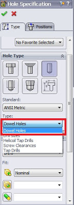
Dowel Holes in Holes Wizard


You can insert standard dowel holes using the Hole Wizard. Dowel holes are used to align components in assemblies. You can choose from standard diameters, or assign custom diameters appropriate to your industry.

To insert the dowel hole: 

1. Click Hole Wizard (Features toolbar).

2. In the Type tab of the Property Manager:

a) Under Hole Type, click Hole.

b) In Type, select Dowels.

c) Set the remaining options as needed.

3. Click OK.


hole specification tool in solidworks


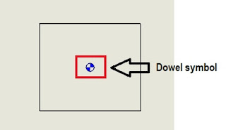
Dowel Pin Symbol Support
There is a new document option for the automatic creation of all dowel pin symbols on view creation as shown below. Additionally, you can automatically insert all dowel pin symbols in a drawing view after view creation.
 
 
dowel pin symbol support
 
 
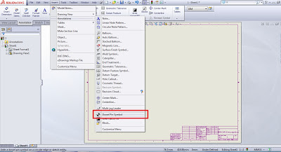
Automatically Inserting Dowel Pin Symbols
To automatically insert dowel symbols after view creation:
1. In a drawing, click Dowel Pin Symbol (Annotation toolbar) or right-click and click Annotations > Dowel Pin Symbol.
2. In the Dowel Pin Symbol Property Manager, under Auto Insert, select For all dowel holes.
3. Set the options.
4. Select one or more drawings views.
5. Click to insert the dowel pin symbols.


solidworks 2013 autmatic inserting of dowel pin


Setting Document Properties for Dowel Pin Symbols

To set the document properties to automatically create all dowel pin symbols on view creation:

1. In a drawing, click Tools > Options.

2. On the Document Properties tab, click Detailing.

3. Under Auto insert on view creation, select:

Dowel symbols -part

Dowel symbols -assembly

4. Click OK.


January 11, 2013

Measure Tool in SolidWorks 2013


Improvements have been made to the Measure Tool functionality and user interface.


Point-to-Point Mode

You can measure the distance between two points on your model. This mode supports snapping to model faces and edges, as well as midpoints, quadrant points, and intersections.


Arc/Circle Measurements

You can create measurements with custom arc conditions. For example, you can measure

the distance from the center of one arc or circle to the outer edge of another. Use drop-down menus on the Measure callouts in the graphics area to toggle between center, maximum, minimum, and custom distances.


Last Used Settings

The Measure tool retains settings from the last time it was used.

History

Click History to see measurements made during the current session of SolidWorks.


User Interface

The Save icon has been replaced with Sensor to indicate the option to create a sensor from the current measurement.


December 27, 2012

SolidWorks 2013 - What's New Series - Searching Options in SolidWorks


You can search for options and settings within Tools > Options.

In the Options dialog box, enter a term in the Search box and select a result. You can search for both System and Document Options.

As you type in the Search string, search results dynamically appear. Click a search result to be taken to the appropriate Options page. Search results are highlighted in the Options dialog box, unless they appear in a drop-down menu.

Note: Your search may not be visible on the Options page due to the type of model you
have open or the current settings.


Get a closer look at SolidWorks 2013 - Request your Trial Today!


December 19, 2012

SolidWorks 2013 - Whats New Feature -VOL II- Previous Release Interoperability


Previous Release Interoperability

You can open SolidWorks 2013 parts and assemblies using SolidWorks 2012 Service Pack 5.

From SolidWorks 2012 on, you can open a future version file in Service Pack 5 of the previous release. For example, in SolidWorks 2013 Service Pack 5 you will be able to open SolidWorks 2014 files. Interoperability is only supported between consecutive releases. For example, you cannot open a SolidWorks 2014 file in SolidWorks 2012 Service Pack 5.

Future version files appear in read-only mode when opened in the previous release. However, once you upgrade to the next version of SolidWorks, all the FeatureManager

design tree data is available. SolidWorks 2013 files have reduced functionality in SolidWorks 2012 Service Pack 5. SolidWorks 2013 files will not have most FeatureManager design tree data when opened in SolidWorks 2012 Service Pack 5. Any actions that require FeatureManager design tree data cannot be performed with a SolidWorks 2013 document open in SolidWorks 2012 Service Pack 5.


The following table summarizes what you can and cannot do in SolidWorks 2012 Service Pack 5:
 
solidworks 2013 previous release operability
 

December 14, 2012

SolidWorks 2013 - What's New features- VOL I

SolidWorks 2013 User Interface changes

Customizing Shortcut Bars

Shortcut bars appear when you press the S key in an open part, assembly, drawing,

or sketch.

To customize a shortcut bar:

1. Click Tools > Customize or right-click the shortcut bar and click Customize.

2. In the Customize dialog box, on the Shortcut Bars tab, click one of the following:

solidworks 2013


So now you can select a Shortcut toolbar for Part, Assembly, Drawing and Sketch as shown in the red box above.


Easier Access to Troubleshooting and Administrative Tools

Troubleshooting and administrative tools are available in the SolidWorks Resources tab

of the Task Pane under SolidWorks Tools.

solidworks 2013 troubleshooting and admin features


Feature Manager Design Tree

In part documents, you can set the Feature Manager Design tree to show features in the order they were created, instead of hierarchically.

Right-click in the Feature Manager Design tree and click Tree Display > Show Flat Tree View. In Flat Tree View, curves, 2D sketches, and 3D sketches are not absorbed into the features that reference them. Instead, they are shown in the order of creation.

Note: Flat tree is only available for parts.

The Unflatten version is shown below.


solidworks 2013 feature manager design tree


Right click on the Part and select Show Flat view option as shown below.


The tree will appear in Flatten state as shown below.


October 16, 2012

SolidWorks 2013 - Design Costing Enhancement

Provides automatic manufacturing cost estimation to support more manufacturing processes and improves access to cost data for downstream manufacturing systems.

- Machined part costing with increased capabilities for turning and mill/turn, improved process recognition, and multibody support
- New APIs to access cost data in the 3D model for downstream manufacturing
- Easily estimate the cost of designs to create more accurate quotations and stay in budget

Get the full details about SolidWorks 2013 on our website


September 12, 2012

SolidWorks 2013 is here!

SolidWorks 2013 is Ready for You!
The 21st release of SolidWorks is here. Powerful new products and design tools, faster modeling, and enhanced collaboration simplify your development process and make you more productive.
 
You are invited to a the SolidWorks 2013 - Launch Event being held at FEA Training Consultants Inc. corporate office in Mississauga on October 11th, 2012.Join us exploring what's new in SolidWorks 2013, followed by presentations on the full suite of SolidWorks  presented by FEA Training Consultants Applications Engineers
DATE:Thursday, October 11,2012
TIME:9am-12pm
LOCATION: FEA Training Consultants Inc. Corporate office