
Discover valuable SOLIDWORKS technical tips, informative videos, and exclusive promotions on the FEA Training Consultants blog. As an authorized SOLIDWORKS Reseller Canada, we offer expert insights and support to help you maximize your design capabilities. Stay informed on the latest SOLIDWORKS features and access to special offers to enhance your engineering solutions.
Showing posts with label solidworks simulation premium. Show all posts
Showing posts with label solidworks simulation premium. Show all posts
August 18, 2015

June 19, 2015
Bolt Fracture
Case Study: Bolt Fracture
Hardware
such as bolts, nuts and washers are generally used for connections and
fixtures. They form an integral part of
the component structural integrity.
Bolts are governed by standards such as ASTM and are typically stamped
with an identifying marking on the head during the manufacturing process. The bolts selected for any application
typically take into account the manner in which it is applied while taking into
account the most prevalent mode of failure.
It follows that it would be in the designer’s best interest to
understand how bolts fail and to avoid those situations.
Consider a
simple bolt modeled in SolidWorks:
Roundhead
Bolt 12mm DIA x 152MM LONG ASTM A307

It is worth
noting that the tensile strength for that grade of bolt is approximately 60,000
PSI. Therefore, using plain carbon steel
as a template, the tensile strength was adjusted accordingly.

Next, we can
set up a test scenario using SolidWorks Simulation where the bolt is fixed at
the top with a base tensile load of 10,000 PSI applied at the bottom

We can now
mesh the bolt

After
running the Static analysis we can do a section plot to understand how the
stress a distributed in the cross section of the bolt. We find that the highest point of stress concentration
occurs at the neck as expected with a value of 28,067 PSI.

Note
that this value is fairly close to yield strength of the material 31,994
PSI. If a stress value approaches the
yield strength, the general assumption of linear behavior of the material
begins to breakdown. Therefore it is in
our best interest to run a non-linear analysis as well.
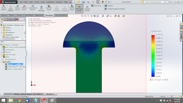
Creating a
new non-linear study and running a similar analysis we find that the actual
stress is approximately 27,197 PSI. This value is less than the linear analysis
but it is still close to yield.


May 20, 2015
Difference between Direct Transfer and Rigid Connection
In SolidWorks Simulation you may define external
loads known as remote loads. Upon
creation of a remote load you have the option of setting it to be either Direct
Transfer or Rigid Connection. What is
the difference?
Consider a
simply supported cantilever composed of two parts: front and back:

We may
create a simulation study that reflects the cantilever beam loading
conditions. It is fixed on one end and
has a load applied on the other end.

We can
simulate the results of this study by excluding half of the beam and applying a
remote load in place.

When
creating a remote load, the user must specify whether it is a direct transfer
or rigid connection

Direct Transfer: Assumes that the component between
the remote force and the connection point is adequately flexible, allowing the structure to deflect. The program decomposes the remote force into
a shear force and coupling moment acting on the connection face. This allows the connection face to distort. Displacements must be within the small
displacement assumption.

Rigid Connection:
Applies rigid links/ connections from the remote load to the connecting
face. As a result when the face deflects,
the face shape is maintained. High
stresses can develop near faces with rigid connections.

The results
of the remote load direct transfer is shown below:

The results
of the remote load rigid connection are shown below:

At first
glance the results are not easily distinguishable; however upon closer
inspection along the vertical axis of the connection face reveals that the
stress distribution from the direct transfer and rigid connection options are
different.


Choosing
whether the remote load will be applied as a direct transfer or rigid
connection will affect the simulation results.
October 9, 2014
Symmetry in SOLIDWORKS Simulation - Guide to Applying Loads & Restraints Appropriately
We are frequently asked here in techsupport what value of a load to apply when using symmetry to cut down on the
size of the overall problem that needs to be solved. As you will see, it is different for how you
handle Force and Pressure loads in Simulation FEA. We can even look into comparing this to the
mass and volume flow rates and velocity or pressure conditions in Flow
Simulation. You can use this blog post
as a guide to help you in modeling up your own problems when you want to use
the benefits of symmetry.
First off, let’s talk a little about when
you can use symmetry. Note that the true
determination of whether you can use symmetry or not depends on the final
results, but that seems a bit contradictory because your looking to solve the
problem and don’t have any results yet.
But there are 3 hints that can clue you into whether symmetry might be
feasible: 1) Obviously the geometry has to be symmetrical, but even if it is
not absolutely symmetrical, such as some details that don’t affect the overall
results and you can assumptively ignore those details . A typical example I recall is the screw for a
cap on the top of a bottle. 2) The
restraints and loads are symmetric. You
should look at this from the perspective of a free-body diagram (FBD), and the
example I use below will help to explain this better. 3) The material is symmetric; a rare case
when considering symmetry is where the materials are different, but it could be
an odd case when working with assemblies.
Again these 3 clues are not fail safe, and
the ultimate determination is in the final results. Using symmetry is a modeling assumption, and
for all analyses, you need to take note and manage your assumptions. If you have some experience with your model
and how it will behave, then this can also help to lead you to a decision if
symmetry is OK to use.

Let’s take the above example of a flat
plate with a hole in the center. It has
a fixed restraint on the left-hand side and a uniform Force applied on the
right-hand side face. When we check the
geometry using a SOLIDWORKS tool: Tools
> Symmetry Check, you can see that the part is symmetric about all three
directions showing that we can choose to keep a 1/8th section of the
original. Now when considering if the
loads and restraints are left-right symmetric, it initially doesn’t seem so
since we have a Force on one end but a Fixed restraint on the other. But from a FBD perspective, you will know
that the restraint will apply an equal and opposite reaction force, so it
actually is a symmetric loading case.
And it is the same material throughout the part, so no problem there.

Note that the face where the load is
applied is cut into four parts, so the question is: Do we need to change the
load? If we think about it, it makes
sense that if the same force were applied to only a quarter of the model, then
the results would be larger… exactly 4 times larger, in this linear test
case. So the conclusion can be made that
we should divide the original force by 4, or F/4. If the original load magnitude was 100, it
should now be 100/4 or 25.
Then, what happens in the case where we
have a Pressure load applied? Pressure
is defined as a force over unit area. If
the area is decreased by 4 times by the symmetry cuts, then the resulting force
that the Pressure exerts is automatically 4 times less. Thus, when we apply a Pressure in the context
of using symmetry, the magnitude of the load does not need to be adjusted.
There is a special case of symmetry that I
need to point out where both the Pressure and Force are unchanged. The special case is when we use the 2D
Simplification tool available in Simulation.
The full load, whether force or pressure, is applied to the edge of the
2D geometry as if it were to be applied to the entire model thickness (in the
case of a plane strain or plane stress problem) or the entire 360o revolve
(in the case of an axisymmetric problem).


Important details not to forget when using
symmetry:
Make sure you apply the
appropriate symmetry conditions on all the faces that have been cut. There is a restraint type called Symmetry
(found under the Advanced restraint types), but this has the limitation that it
can only be applied to faces that are orthogonal (90o) to one
another, hence will not work on a pie sliver type of cut, for example. So it’s best to know that actual definition
of a symmetry restraint, in case that you need to apply manually using the Use
Reference geometry restraint type, is that the face can only translate on the
plane and cannot rotate out of plane. In
other words, the Normal translation and the other two directional Rotational
degrees-of-freedom are held to zero.
(Aside: Did you know that you can apply an Anti-Symmetric
restraint by applying just the opposite conditions as described above?)
Symmetry can be used for the
following study types: linear Static, Thermal and Nonlinear. It SHOULD NOT BE USED in a Frequency,
Buckling, Drop Test or Linear Dynamic study.
The results from all of these will most definitely have non-symmetric
responses. If you use symmetry in a
Frequency study, for example, you will only be able to extract the resonant
frequencies which are symmetric, and you would miss all of the non-symmetric
shapes.
For a Thermal study, when a
face has no condition set on it, it is defined as adiabatic, that is no heat
enters or leaves through this face, hence the symmetric condition is set by not
defining a condition to it. A Heat Power
load (in Watts) is absolute, so like a Force, has to be divided. A Heat Flux (in W/m2) is an
integrated over an area, so like a pressure does not need to be changed. Temperature is temperature, like a prescribed
value, so no need to change as well.
Final Stress Results from the plate with a hole using a proper symmetry loading conditions.

Final Stress Results from the plate with a hole using a proper symmetry loading conditions.
February 5, 2014
What's new in SolidWorks Simulation 2014
With every year's major release in SolidWorks, the enhancements that is made in all modules of SolidWorks Simulation 2014 (SolidWorks Simulation Professional, SolidWorks Simulation Premium and SolidWorks Flow Simulation) is truly outstanding.
The SolidWorks Simulation 2014 release focus on four important theme:
Mirror results about planes of symmetry
 Save multiple SolidWorks Flow Simulation output charts in a single edrawing.
Benefits:
SolidWorks Simulation Performance Enhancements to :
The SolidWorks Simulation 2014 release focus on four important theme:
 Boost Productivity with Intelligent Tools

- Automatically convert Toolbox Fasteners to bolt connectors
- New Bolt Connectors Symbol
- Easier Simulation setup time
- Leverage CAD Simulation
- Improve productivity of Product Engineers
 Perform comprehensive simulations across consistent solution

Leverage ECAD thermal properties
- Import thermal properties from Circuit Works in SolidWorks Flow Simulation
- Import PCB layers definition from Circuit Works in SolidWorks Flow Simulation
- Streamline product development process
- Enhance the user experience with SolidWorks Solutions.
 Import Residual Stress from SolidWorks Plastics

- Import In-Molding Residual Stress (the stress generated before ejection) from SolidWorks Plastics.
- Perform Structural Analysis taking in account molding stresses.
- Provide complete performance test capabilities.
- Consistency of the global simulation tools.
Acheive greater insight with Simulation results

- Allows user to mirror results about planes of symmetry (planar,cyclic)
- Ease post processing of Complex symmetrical models
- Facilitate the sharing of simulation results with people unfamiliar with Simulation.
Results Comparison Across Configurations
 Allow the user to compare simulation results across different configurations.
- Benefits :
- Ease comparison of design scenarios
- Enable user to focus on his research to best design
Better eDrawings support of CFD results
Save multiple SolidWorks Flow Simulation output charts in a single edrawing.Benefits:
- Ease Communication with CFD results
- offer consistency with solidworks simulation
 Performance
SolidWorks Simulation Performance Enhancements to :
- Faster file open with Simulation Active
- Large problem with Large problem direct sparse solver - Multi -Core Support
- Direct Sparse solver - upto 40% seep up for in-core problems
- Large speed up in the Interactive Solver (FFE +) - Multi-Processor, Contact convergence
Subscribe to:
Posts (Atom)