Showing posts with label sketching. Show all posts

December 10, 2015

Sketching Improvements in SOLIDWORKS 2016

IMPROVEMENTS IN SOLIDWORKS SKETCHING 2016

 Sketching is perhaps one of the core functionalities in the SolidWorks software.  Sketches allow a user to create 2 dimensional entities that may be used to create complex features.  It is a tool that helps the designer shape the part into the correct geometry.  With SolidWorks 2016 there have been improvements to the sketching abilities to make modeling easier.

Consider the following Valve

sketching solidworks


By opening up the base sketch used in the revolve feature to create the valve body we have the following sketch:


sketch solidworks

HIDE SKETCH DIMENSIONS:

Sketches become more complex with the addition of geometrical features.  There may be times when the dimensions constraining the sketch become cluttered to view in the graphical area.  In SolidWorks 2016 there is a new tool to hide sketch dimensions.  This is found under Tools> Hide/Show/ Hide Sketch Dimensions. By applying this filter to the graphical viewing area, it makes it much easier for the designer to inspect the current state of the sketch.

hide/show/hide sketch dimensions

sketching in solidworks 2016


MIDPOINTS:

When a designer is dimension or adding relations to a sketch, the midpoint is a useful entity to have available.  Midpoints are now automatically selectable without explicitly defining a midpoint entity.  This change helps expedite the sketching process allowing designers to fully define a sketch in fewer steps than before.

sketching midpoint


SMART DIMENSION:


In addition, it is no longer necessary to select the smart dimension icon before clicking on the entities that require dimension.  Instead, designers can now select the entities of interest and a fly out menu will appear beside the mouse.  Designers may now select the Smart Dimension icon from that menu and the software will provide the appropriate dimension for the entities selected.  

smart dimension solidworks sketching\


sketching impovements in solidworks 2016


INSTANT 2D:

Another useful tool is Instant 2D which is a feature that allows users to modify the value of a dimension with a single click.  Instant 2D can be found on the sketch toolbar.

instant 2D solidworks sketching


July 28, 2015

How to use "Curve through XYZ Points"?

Curve through xyz points

Data can be provided to the designer in a variety of ways from contract drawings, field measurement, word of mouth etc.  In the case of field measurement or established geometries, the data can come in the form of a plotted coordinate system. 

Let us consider the profile of an airfoil.  The geometrical features of an airfoil effect the flow and thus performance of the airfoil in operation.  It is important to model the geometry as accurately as possible.  The geometry is given in the form of an x-y coordinate system.  

xy coordinates


It is worth noting that an additional column was added with all zeros in order to represent the dimensions for the Z plane.  The three column as given in excel format is not as useful, therefore we can copy the data by selecting the columns and selecting copy and paste it in a text document.

curve through xyz points


imported curve solidworks


Save the text document since you will need to select it soon.

 Next we can start a new part in SolidWorks.  In order to bring the airfoil into SolidWorks you can sketch individual points and draw a spline connecting all the points.  This manual method is repetitive, labor intensive and time consuming.  A more efficient method would be to use the “Curve through XYZ Points” tool from the feature tab.

curve through xyz points


After selecting “Curve through XYZ Points”, click on browse and select the text file with the coordinates that was created.

xyz points solidworks


  Upon selection you should see the points and data values populating the X, Y and Z coordinates.  Select “OK”.

curve through xyz points


  Now you should have a full accurate curved geometry that was constrained by the X,Y and Z coordinates that were imported.  Creating this curve using this method is significantly quicker than manually plotting each point and connecting them with a spline.  “Curve through XYZ Points” is one of many features that makes solid modeling faster and more efficient in SolidWorks.

June 10, 2015

Blocks in Sketch

Sketching skills form the fundamental basis of SolidWorks software.  Parts, features, geometries and patterns are all dependent on the first initial sketch.  Therefore learning tricks and shortcuts can potentially positively impact your work flow.  

 Consider a simple part composed of an extruded rectangle as shown below:

sketching solidworks


There will be times when there are repetitions of complex sketch parts.  Whenever there are repetitions you may use SolidWorks pattern features to avoid recreating the part over and over or alternatively you  may choose to use a block.
  The original rectangle drawn requires a curve added to two edge.  The curve has been drawn separately from the part as shown:

solidworks pattern feature


Please note it is undefined and without reference.  Select all entities composing the curve, right click and select “Make Block” from the quick menu.  

blocks in sketch


Select the green check mark to accept the creation of the block

solidworks sketching


The curve now exists as a block and is free to move as a single unit. 

sketching in solidworks


You may copy and paste multiple copies of the block in the sketch.  Please note that if you edit the block, all instances will update to reflect the change.  It is also worth noting that the lines and points on the block may accept relations just like any sketch such as coincident relation and horizontal relation.  Two copies of the block have been added and applied to the top and bottom portion of our part.  A small sketched line completes a closed contour between the block and the original sketch.


blocks in sketch


Completing our changes we may leave the sketch window and rebuild the feature to show the boss-extrude has accepted the new sketch with two instances of a block. 

block sketch solidworks


This saves us the time and effort to recreate the same sketch multiple times.

March 13, 2015

Sketch Xpert in SolidWorks

Sketch Xpert

SolidWorks is a feature-based software and many of those features are created from sketches.  Sketches are composed of dimensions and relations to maintain geometry.  A blue sketch would indicate an undefined sketch whereas a black sketch would indicate fully defined sketch.  Image 1 is a good example of a fully defined sketch.

Sketch Xpert Image 1 (Defined Sketch):
sketch xpert property manager


There will be instances where a sketch will generate a conflict due to conflicting conditions. Also known as an over defined sketch.  In our case, Image 2 shows a tangent relation being added to a line and circular entity.

Sketch Xpert Image 2:
solidworks sketch xpert


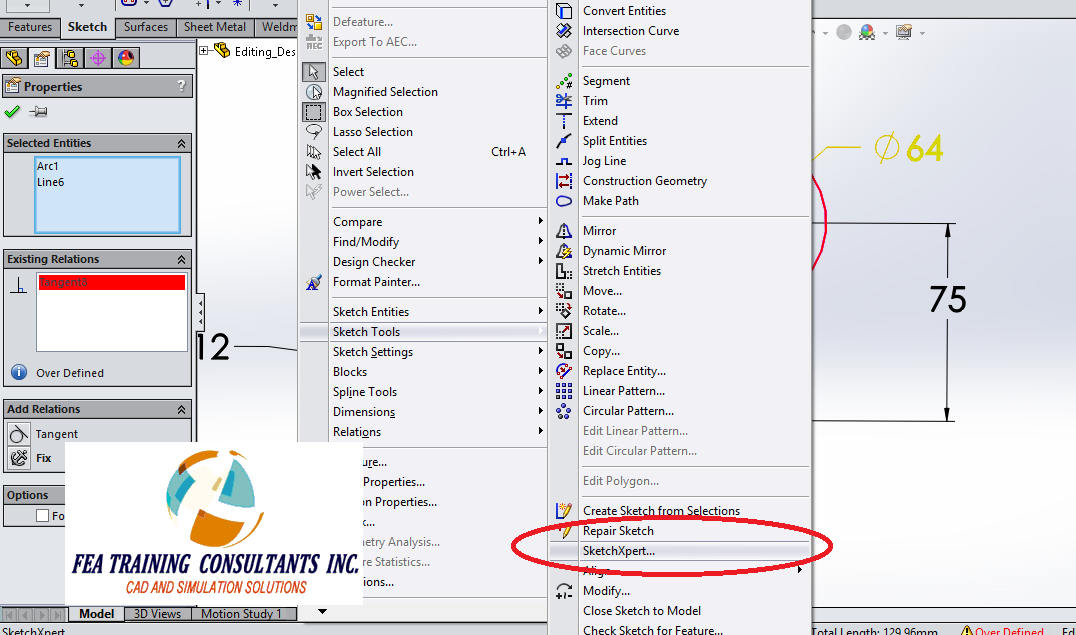
In cases like these we may use the Sketch Xpert tool.  The Sketch Xpert Tool is found from Tools > Sketch Tools > Sketch Xpert as per image 3.

Sketch Xpert Image 3:
sketch xpert2


Once Sketch Xpert is selected, click “Diagnose” and Sketch Xpert will search for a solution.

Sketch Xpert Image 4:
diagnose sketch xpert


Under “Results” you may scroll through different solutions that Sketch Xpert has created in order to solve the conflicting over defined sketch.

Sketch Xpert Image:5
solidworks sketch tool


Sketch Xpert Image 6:
sketch in solidworks


In this case we select the geometry that best represents what we wanted to achieve and select “Accept”. The sketch is no longer over defined and may be used normally.


Sketch Xpert Image 7:
solidworks sketch


March 5, 2015

Creating a Custom Detailed View in SolidWorks

CREATING A CUSTOM DETAILED VIEW

When a part is modeled in SolidWorks it exists as a virtual object as per Figure 1.

Figure1:
part modeling solidworks


That information is traditionally conveyed to manufacturing by means of an engineering drawing.  The parametric nature of the Solidworks software allows for modifications of the part model to instantly update the part drawings.  Furthermore, more complex assemblies may have their Bills of Material updated on the fly.  An example of a simple engineering drawing is shown in Figure 2 (dimensions removed for clarity).

Figure 2:
solidworks drawings


Traditional use of the detailed view allows for a circular cut out and enlargement of the viewing section.  In some cases it is beneficial to create a custom or modifiable shape that will suit the geometry of your part.  In this case I have chosen a simple rectangle for illustration purposes.  Please bare in mind that any closed contour will work as well.  Begin by sketching your contour around the section you would like to detail as shown in Figure 3.

Figure 3:
sketching solidworks


Once the sketch is complete, select the “View Layout” tab and select “Detail View”.  This will create a detailed view based on the contour that you sketched.  In this case the detail view is a rectangle instead of the default circle as shown in Figure 4.

Figure 4:
custom detailed view in solidworks


This trick will help you save space and work with better formatting in your engineering drawings.  

January 28, 2015

New in SolidWorks 2015- Sketching (Part 2)

New in SOLIDWORKS 2015 - SKETCHING


EQUIDISTANT POINTS AND SEGMENTS

You can create equidistant points and segments in a sketch. We will divide the line below in 5 segments using the Segment command highlighted in red box

SKETCH SOLIDWORKS


In the Segment tool we have to select the entity that we want to divide. Then we have the option to select Sketch points or Sketch segments and the number of instances. In our case we selected the line as the entity to divide and Sketch segment option with 5 segments to divide.


As shown below the line got divided into 5 segments and we can select any one of the segment. Here the first segment is selected and so it’s highlighted in orange color.


MIDPOINTLINE SOLIDWORKS


Below is an example of using Segment command with sketch point’s option. Here we are creating 8 points on the circle’s circumference.


As shown below when the circle is selected its one complete segment with 8 points distributed equally.


MIDPOINT LINE OPTION

There is a new type of line in the Line command and it’s the Midpoint line option as shown below. You can create a line that is symmetrical from the midpoint of the line


We started the sketch line from the origin using the Midpoint line option and as shown below it’s symmetrical on both sides from the origin.


LINE PROPERTIES SOLIDWORKS