Showing posts with label CAE. Show all posts

May 20, 2015

Difference between Direct Transfer and Rigid Connection

In SolidWorks Simulation you may define external loads known as remote loads.  Upon creation of a remote load you have the option of setting it to be either Direct Transfer or Rigid ConnectionWhat is the difference?

Consider a simply supported cantilever composed of two parts: front and back: 

solidworks simulation


We may create a simulation study that reflects the cantilever beam loading conditions.  It is fixed on one end and has a load applied on the other end.

simulation study in solidworks simulation


We can simulate the results of this study by excluding half of the beam and applying a remote load in place.  

load conditions in solidworks simulation


When creating a remote load, the user must specify whether it is a direct transfer or rigid connection

direct transfer vs rigid connection in solidworks simulation


Direct Transfer: Assumes that the component between the remote force and the connection point is adequately flexible, allowing the structure to deflect.  The program decomposes the remote force into a shear force and coupling moment acting on the connection face.  This allows the connection face to distort.  Displacements must be within the small displacement assumption.

remote force - solidworks simulation


Rigid Connection:   Applies rigid links/ connections from the remote load to the connecting face.  As a result when the face deflects, the face shape is maintained.  High stresses can develop near faces with rigid connections.


rigid coneections- solidworks simulation


The results of the remote load direct transfer is shown below:

remote load direct transfer


The results of the remote load rigid connection are shown below:

rigid connection-solidworks simulation


At first glance the results are not easily distinguishable; however upon closer inspection along the vertical axis of the connection face reveals that the stress distribution from the direct transfer and rigid connection options are different.

direct transfer-solidworks simulation


rigid connection-solidworks simulation


Choosing whether the remote load will be applied as a direct transfer or rigid connection will affect the simulation results.


February 20, 2015

Enhanced Turbulence Modeling in SolidWorks Flow Simulation

SolidWorks® Flow Simulation is a powerful, intelligent, and easy-to-use computational fluid dynamics (CFD) program that facilitates the work of product engineers who use SolidWorks 3D CAD software for 3D design creation. This paper details the approach and theory behind turbulence modeling as used in SolidWorks Flow Simulation to simulate complex industrial turbulent flows with heat and mass transfer.
Download the Whitepaper to learn more:

October 17, 2014

Frequency Analysis: Super Frequency Study

“Super Frequency” study type

There are many different types of studies that you can run in SOLIDWORKS Simulation, such as Linear Static, Thermal, Fatigue, Nonlinear and Drop Test, but there is one study type that is sort of a “super” type.  The super study that I’m talking about is a Frequency study type.


Why it’s super is that it has multiple applications where it is useful:

1 – Determining natural frequencies


         The typical usage of a Frequency analysis is to determine the natural resonances of a system, see example listing below.  You all may be familiar with some famous examples, such as the Tacoma Narrows bridge, where a system’s vibration will be amplified when it is excited by an external force at (or near) one of its resonant points.  And every system theoretically has an infinite number of resonant frequencies that are at increasingly higher values, so everything you design has a lot of points where it can fail.  If you don’t think that your design will undergo vibration during use, you should consider how your products get transported often by many vehicles, either by land or air, that subject it to a wide range of external frequencies getting to its final destination.
list modes on frequency analysis


2 – Characteristic movement of system


      Another great result to obtain from a Frequency simulation is the characteristic shapes that the system wants to move.  This gives you an indication of the relative stiffness in each direction, and where some areas of the design may be “weaker” (or more susceptible to stress) than others.  As you can see in the example below for an engine mounting frame, where the engine is replaced by a remote mass point, the first mode shape shows that has a tendency to want to rock to-and-fro and thus tear itself away from the base.  While it cannot be determined from this analysis whether it will actually tear away, but you can plainly see that special attention should be placed on the horizontal braces and its bolted connections to the base.  And there are multiple characteristic shapes that can be evaluated

solidworks simulation

3 – Troubleshooting tool


      One might not think of running a simulation as a troubleshooting measure for the FEA modeling, but a Frequency analysis can also help in this regard.  You can setup the model similarly as you would in say a linear Static analysis; the advantage of starting it as a Frequency study is that even if you have issues with insufficient restraints or connecting all the parts in your assembly, it will still solve albeit with some rigid body motions yielding a nearly 0 (zero) Hz frequency.  This information is valuable to working out the model issues.  Once you have it all figured out in the Frequency study, all the setup features can be copied to another study by ctrl+mouse select plus drag-and-drop them into the tab (at the bottom) for that study.
frequency anlaysis


4 – Basis for many other types of analysis


     A Frequency study is also the underlying basis for the following study types: linear Buckling and the four Linear Dynamic studies (Time History, Harmonic, Random Vibration (or PSD), and Response Spectrum analysis).  The definition of a linear Buckling study is when the transverse stiffness goes to zero under a compressive loading case, and this can be represented by the first natural frequency, which for a simple column example is a half-sine wave.  The combined response from summing up all of the resonant frequencies and associated characteristic mode shapes provides a very efficient way of performing a Linear Dynamic analysis.

solidworks simulation

September 30, 2014

SolidWorks Simulation:Meshing of failed Parts

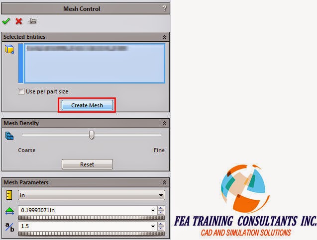
If you have part(s) that fail to mesh in an assembly model, the part icon in the Simulation Parts list will be indicated by a red hashed icon, as shown in the image below.  But with the latest releases of SOLIDWORKS Simulation (2011 and above), you can fix this issue by right-clicking the part and choosing to Create Mesh for that part alone. 


This selection will take you into the Mesh Control dialog, see image below, where you can adjust settings for the mesh size if you want, but simply clicking the Create Mesh button here will re-mesh only that part but still in the context of the assembly.


You are reminded of this fact by a pop-up telling you what is happening, see image below.  (1) It creates a mesh control in the tree, and regardless of the mesher previously used, it will mesh the failed part using the Curvature based mesher. 
(2) It will also automatically create Contact Sets using faces that are touching neighboring parts.  Most likely the reason why the part failed to mesh in the first place was that the differences in part sizes prevented it from maintaining a compatible mesh.  If there was interference between parts, another reason for parts failing to mesh, then you need to manually define the Contact Set to appropriately define their interaction


When all parts have successfully meshed, the top level Part icon will have a check indicating that everything is meshed, see image below.