Showing posts with label Linear Static Analysis. Show all posts

June 19, 2015

Bolt Fracture

Case Study: Bolt Fracture 

Hardware such as bolts, nuts and washers are generally used for connections and fixtures.  They form an integral part of the component structural integrity.  Bolts are governed by standards such as ASTM and are typically stamped with an identifying marking on the head during the manufacturing process.  The bolts selected for any application typically take into account the manner in which it is applied while taking into account the most prevalent mode of failure.  It follows that it would be in the designer’s best interest to understand how bolts fail and to avoid those situations.

Consider a simple bolt modeled in SolidWorks:

Roundhead Bolt 12mm DIA x 152MM LONG ASTM A307

bolt in solidworks


It is worth noting that the tensile strength for that grade of bolt is approximately 60,000 PSI.  Therefore, using plain carbon steel as a template, the tensile strength was adjusted accordingly.

tensile strength of bolt


Next, we can set up a test scenario using SolidWorks Simulation where the bolt is fixed at the top with a base tensile load of 10,000 PSI applied at the bottom

solidworks simulation of bolt


We can now mesh the bolt

meshing the bolt in solidworks simulation


After running the Static analysis we can do a section plot to understand how the stress a distributed in the cross section of the bolt.  We find that the highest point of stress concentration occurs at the neck as expected with a value of 28,067 PSI.  

static analysis of bolt in solidworks simulation


Note that this value is fairly close to yield strength of the material 31,994 PSI.  If a stress value approaches the yield strength, the general assumption of linear behavior of the material begins to breakdown.  Therefore it is in our best interest to run a non-linear analysis as well.

stress anlaysis of bolt


Creating a new non-linear study and running a similar analysis we find that the actual stress is approximately 27,197 PSI. This value is less than the linear analysis but it is still close to yield. 
Given these results it would be in the designer’s best interest to either reduce the load, increase the bolt diameter or chose a higher grade bolt.
Sometimes bolt failure can occur due to other circumstances as well.  Specifications such as how much a bolt must be tensioned at installation can make a difference.  In other cases large batches can yield bolts with manufacturing defects which may fail below the yield stress.  


October 17, 2014

Frequency Analysis: Super Frequency Study

“Super Frequency” study type

There are many different types of studies that you can run in SOLIDWORKS Simulation, such as Linear Static, Thermal, Fatigue, Nonlinear and Drop Test, but there is one study type that is sort of a “super” type.  The super study that I’m talking about is a Frequency study type.


Why it’s super is that it has multiple applications where it is useful:

1 – Determining natural frequencies


         The typical usage of a Frequency analysis is to determine the natural resonances of a system, see example listing below.  You all may be familiar with some famous examples, such as the Tacoma Narrows bridge, where a system’s vibration will be amplified when it is excited by an external force at (or near) one of its resonant points.  And every system theoretically has an infinite number of resonant frequencies that are at increasingly higher values, so everything you design has a lot of points where it can fail.  If you don’t think that your design will undergo vibration during use, you should consider how your products get transported often by many vehicles, either by land or air, that subject it to a wide range of external frequencies getting to its final destination.
list modes on frequency analysis


2 – Characteristic movement of system


      Another great result to obtain from a Frequency simulation is the characteristic shapes that the system wants to move.  This gives you an indication of the relative stiffness in each direction, and where some areas of the design may be “weaker” (or more susceptible to stress) than others.  As you can see in the example below for an engine mounting frame, where the engine is replaced by a remote mass point, the first mode shape shows that has a tendency to want to rock to-and-fro and thus tear itself away from the base.  While it cannot be determined from this analysis whether it will actually tear away, but you can plainly see that special attention should be placed on the horizontal braces and its bolted connections to the base.  And there are multiple characteristic shapes that can be evaluated

solidworks simulation

3 – Troubleshooting tool


      One might not think of running a simulation as a troubleshooting measure for the FEA modeling, but a Frequency analysis can also help in this regard.  You can setup the model similarly as you would in say a linear Static analysis; the advantage of starting it as a Frequency study is that even if you have issues with insufficient restraints or connecting all the parts in your assembly, it will still solve albeit with some rigid body motions yielding a nearly 0 (zero) Hz frequency.  This information is valuable to working out the model issues.  Once you have it all figured out in the Frequency study, all the setup features can be copied to another study by ctrl+mouse select plus drag-and-drop them into the tab (at the bottom) for that study.
frequency anlaysis


4 – Basis for many other types of analysis


     A Frequency study is also the underlying basis for the following study types: linear Buckling and the four Linear Dynamic studies (Time History, Harmonic, Random Vibration (or PSD), and Response Spectrum analysis).  The definition of a linear Buckling study is when the transverse stiffness goes to zero under a compressive loading case, and this can be represented by the first natural frequency, which for a simple column example is a half-sine wave.  The combined response from summing up all of the resonant frequencies and associated characteristic mode shapes provides a very efficient way of performing a Linear Dynamic analysis.

solidworks simulation

October 9, 2014

Symmetry in SOLIDWORKS Simulation - Guide to Applying Loads & Restraints Appropriately

We are frequently asked here in techsupport what value of a load to apply when using symmetry to cut down on the size of the overall problem that needs to be solved.  As you will see, it is different for how you handle Force and Pressure loads in Simulation FEA.  We can even look into comparing this to the mass and volume flow rates and velocity or pressure conditions in Flow Simulation.   You can use this blog post as a guide to help you in modeling up your own problems when you want to use the benefits of symmetry.
First off, let’s talk a little about when you can use symmetry.  Note that the true determination of whether you can use symmetry or not depends on the final results, but that seems a bit contradictory because your looking to solve the problem and don’t have any results yet.  But there are 3 hints that can clue you into whether symmetry might be feasible: 1) Obviously the geometry has to be symmetrical, but even if it is not absolutely symmetrical, such as some details that don’t affect the overall results and you can assumptively ignore those details .  A typical example I recall is the screw for a cap on the top of a bottle.  2) The restraints and loads are symmetric.  You should look at this from the perspective of a free-body diagram (FBD), and the example I use below will help to explain this better.  3) The material is symmetric; a rare case when considering symmetry is where the materials are different, but it could be an odd case when working with assemblies.

Again these 3 clues are not fail safe, and the ultimate determination is in the final results.  Using symmetry is a modeling assumption, and for all analyses, you need to take note and manage your assumptions.  If you have some experience with your model and how it will behave, then this can also help to lead you to a decision if symmetry is OK to use.
FEA SolidWorks Simulation


Let’s take the above example of a flat plate with a hole in the center.  It has a fixed restraint on the left-hand side and a uniform Force applied on the right-hand side face.  When we check the geometry using a SOLIDWORKS tool: Tools > Symmetry Check, you can see that the part is symmetric about all three directions showing that we can choose to keep a 1/8th section of the original.  Now when considering if the loads and restraints are left-right symmetric, it initially doesn’t seem so since we have a Force on one end but a Fixed restraint on the other.  But from a FBD perspective, you will know that the restraint will apply an equal and opposite reaction force, so it actually is a symmetric loading case.  And it is the same material throughout the part, so no problem there.


symmetry in solidworks simulation

Note that the face where the load is applied is cut into four parts, so the question is: Do we need to change the load?  If we think about it, it makes sense that if the same force were applied to only a quarter of the model, then the results would be larger… exactly 4 times larger, in this linear test case.  So the conclusion can be made that we should divide the original force by 4, or F/4.  If the original load magnitude was 100, it should now be 100/4 or 25.
Then, what happens in the case where we have a Pressure load applied?  Pressure is defined as a force over unit area.  If the area is decreased by 4 times by the symmetry cuts, then the resulting force that the Pressure exerts is automatically 4 times less.  Thus, when we apply a Pressure in the context of using symmetry, the magnitude of the load does not need to be adjusted.
There is a special case of symmetry that I need to point out where both the Pressure and Force are unchanged.  The special case is when we use the 2D Simplification tool available in Simulation.  The full load, whether force or pressure, is applied to the edge of the 2D geometry as if it were to be applied to the entire model thickness (in the case of a plane strain or plane stress problem) or the entire 360o revolve (in the case of an axisymmetric problem).


symmetry check


In SOLIDWORKS Flow Simulation, currently you can do a half or quarter symmetry solution by only changing the Computational Domain options, i.e. you don’t actually cut the model but instead change the bounding box where the calculation is performed.  The values for Mass and Volume Flow Rate boundary conditions are absolute (akin to a Force in FEA), So you will need to reduce the flow rate by ½ or ¼ if you are using a half or quarter domain, respectively.  Pressure is the same as pressure in a structural calculation, so no adjustment needed there.  What about velocity?  Velocity does not need to be changed either; if you think about it from a flow rate perspective, where the rate needs to be reduced because the amount of fluid moving through that opening changes, but the velocity of the fluid will always be the same.


Important details not to forget when using symmetry:
 Make sure you apply the appropriate symmetry conditions on all the faces that have been cut.  There is a restraint type called Symmetry (found under the Advanced restraint types), but this has the limitation that it can only be applied to faces that are orthogonal (90o) to one another, hence will not work on a pie sliver type of cut, for example.  So it’s best to know that actual definition of a symmetry restraint, in case that you need to apply manually using the Use Reference geometry restraint type, is that the face can only translate on the plane and cannot rotate out of plane.  In other words, the Normal translation and the other two directional Rotational degrees-of-freedom are held to zero.  (Aside: Did you know that you can apply an Anti-Symmetric restraint by applying just the opposite conditions as described above?)

Symmetry can be used for the following study types: linear Static, Thermal and Nonlinear.  It SHOULD NOT BE USED in a Frequency, Buckling, Drop Test or Linear Dynamic study.  The results from all of these will most definitely have non-symmetric responses.  If you use symmetry in a Frequency study, for example, you will only be able to extract the resonant frequencies which are symmetric, and you would miss all of the non-symmetric shapes.

For a Thermal study, when a face has no condition set on it, it is defined as adiabatic, that is no heat enters or leaves through this face, hence the symmetric condition is set by not defining a condition to it.  A Heat Power load (in Watts) is absolute, so like a Force, has to be divided.  A Heat Flux (in W/m2) is an integrated over an area, so like a pressure does not need to be changed.  Temperature is temperature, like a prescribed value, so no need to change as well.


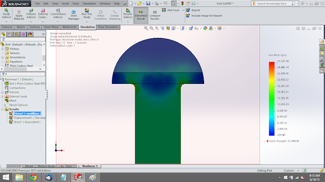
Final Stress Results from the plate with a hole using a proper symmetry loading conditions.


results using proper symmetry loading conditions

October 1, 2014

SOLIDWORKS Simulation Standard (FEA) software bundle now available


SOLIDWORKS Simulation Standard

is a new offering in the 2015 Simulation product suite.  The package includes the capability to run Linear Static analysis on assemblies, time-based Motion for mechanism design, Fatigue failure analysis and simulation-driven design Trend Tracker.  It enables a user at any level of the SOLIDWORKS design software to add some essential simulation capabilities to their toolset.


simulation standard features


Linear Static analysis

helps you to validate product performance and safety factors using finite element analysis (FEA) to perform structural simulation.  It is a primary tool to assess the displacement, strain and stress on parts and assemblies.  You can perform analysis of solid bodies, sheet metal parts and weldments of long slender beams all in the same assembly.


static stress analysis


Time-based Motion

allows you to evaluate the performance, using rigid body motion analysis, of assembly mechanisms, and can aid in the sizing of springs, dampers, motors and actuators.  Motion automatically reuses the intelligence built into the assembly mates, and can be combined with defined 3D part contact, to accurately determine the physical movements of an assembly under load using a robust physics-based solver. With the assembly motion calculated, the forces can be transferred directly into a structural analysis to assess the stress of a component due to the motion.

motion analysis in solidworks

Fatigue is the most common type of failure for materials, especially metals, accounting for about 50-90% of all failures and occurs in all industries. 

Fatigue analysis

allows you to design for the durability of your parts for loads it will typically encounter over its life, rather than just for a large catastrophic load that rarely would occur in a worst case scenario.  With this module you can examine two types of repeating loads, cyclic or random, for single or multiple events occurring over a large number (in the thousands or millions) of times over the life of the part.  Using the material S-N curve, it computes the contribution of the events by using Miner’s rule (cyclic) or Rainflow counting (random) to report the total cumulative damage (as a percentage) that the design has undergone, and for a single event will report the predicted life.

fatigue analysis


Trend Tracker

is a very powerful design tools that lets you easily test many design ideas without being restricted to how the changes are made.  Setting the baseline model starts tracking multiple design variables, such as mass and max stress, so that any design iterations are compared back to it and trends can be evaluated by viewing a design journal or trend graphs.  When combined with a Design Insight plot, the Trend Tracker tool gives you another level of understanding of your design that intuition or experience cannot provide.  That’s a lot of bang for your buck!
.

trend tracker

Follow the SOLIDWORKS Simulation link to see all of the products that FEA Training Consultants Inc. provides.