WELDMENT CUT LIST
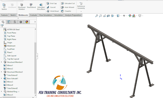
Last blog we explored the creation of a simple weldment frame. A natural extension to the weldment features is the cut list which lists all the parts and lengths required to make the weldment. It is very similar in nature to a bill of material. Consider our weldment frame:

We’ll start
by creating a drawing for this weldment by first going to File> Make Drawing
from Part.
A simple
drawing is created with a plan, elevation, side and isometric view. Now we would like to insert our cut list.
In order to
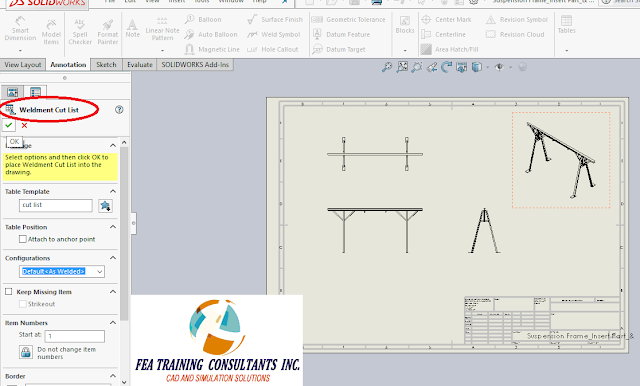
insert a cut list go to Annotation> Tables > Weldment Cut List
In the
Weldment Cut List Property box, the designer is able to change and modify
various parameters such as the table name/ template, position, etc.
Once a table
has been completed, the designer will find a list of sections including
description, quantity, length and item number.
You might notice that there are special entries such as plate and
Weld-On Ring. The Weld-On Ring is a
special unique part therefore has a separate entry, however the plate was the
base plate we modeled. The cut list
conveniently lists the dimensions of the plate.
These dimensions are controlled by a bounding box.
If the
designer needs to make changes or even edit the bounding box, it is done simply
by going back to the model, expand the cut list and right click the part of
your choice and select Edit Bounding Box.
This is a very useful feature to capture items such as base plates,
stiffeners and gussets, all very common structural elements.
Weldment
features in SolidWorks makes designing quick and easier for designers. Weldment is available for all versions of
SolidWorks; Standard, Professional and Premium.


No comments:
Post a Comment