SHEET METAL FLANGE
Sheet metal
and weldments are two very popular tabs for the manufacturing industry
specifically with metal. Last blog we
worked through an example of a simple sheet metal box, now let’s consider a circular flange:
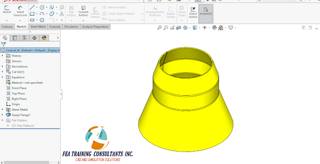


The circular
flange is conical in shape; therefore we want to take advantage of the sweep
function when creating this part. We
start by first sketching the profile on the front plane.

Ensure that
the sketch is fully defined which means it is all black in the graphical
window. Since this part involves a
revolution, be sure to create a vertical construction line about the center of
revolution.

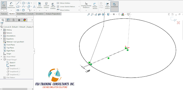
Following
the first sketch, create a second sketch on the top plane to act as the
sweeping path. Note that there is a one
degree gap break in the line shown in the figure. This allows the flange to be created from a
single rolled piece of sheet metal.

Next, we
want to select the Swept Flange feature by going to Insert > Sheet Metal
> Swept Flange

Once the
Swept Flange function is selected, select the two sketches, Sketch1 and
Sketch2, as the profile and path, as well as the construction line as the
cylindrical axis.

Upon
completion, apply the feature and we should have our completed sheet metal
flange part. This is a sheet metal part
and as such will also provide the designer with a flat pattern as well to cut
and form.
Sheet metal
features in SolidWorks makes designing quick and easier for designers. Sheet metal is available for all versions of
SolidWorks; Standard, Professional and Premium.
No comments:
Post a Comment