What's New in SolidWorks 2016?
SolidWorks Sheetmetal - Edit Flange Profile
SolidWorks sheet metal has been a very useful tool in creating parts that require flattened patterns. The flat patterns are the shapes used to cut out parts that when folded form the finished product. One of the most common tools in sheet metal is the edge flange.
Consider the
following sheet metal part:
We want to
add a flange to cover the front of this part, therefore we can use the edge
flange tool.
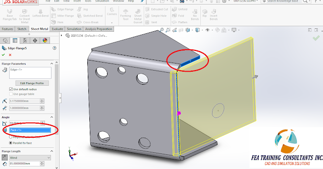
When we
apply an edge flange to the selected edge, an extension is created
perpendicular by default to the original sheet.
This is
adjusted by selecting a reference face for the flange to be set parallel.
When
creating a flange it is important to consider the flange position. This means where the bend occurs, in this
case we can the bend to be on the outside.
This elevates the flange as to not cause interference with the two
pre-existing flanges on the side.
Normally to
extend the flange outside of the square shape a designer would need additional
sketches.
However SolidWorks 2016 brings
a new functionality called “Edit Flange Profile”. By selecting Edit Flange Profile it allows
the user to manipulate and modify the sketch shown. This includes the blue undefined lines as
well as the black fully defined lines as shown below:
Applying the
sheet metal feature allows for the edge flange to be created without any
additional sketches required.
The
new Edit Flange Sketch functionality is designed to help designers be more
efficient and therefore safe time when modeling sheet metal in SolidWorks 2016.
To learn more, or to get started with SolidWorks contact FEA.


No comments:
Post a Comment