ASSEMBLY MODELING
Conventional modeling practices allow users
to create a part and combine multiple parts in an assembly. It is worth knowing that this is not the only
approach to modeling. You have the option to model straight from assembly mode.
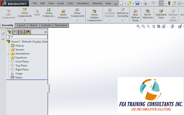
Consider a
new assembly:
From this
new assembly select Insert > Component > New Part. A new generic part file will be created in
the feature manager design tree:
Select your
part, right click and select “Edit Part”
In this
example let’s sketch a simple rectangle on the top plane
Extrude the
rectangle to create a solid. Please note
that we are still in Assembly mode, However, we are working under the “Edit
Component” feature.
Similarly we
can insert a new part and sketch on a rectangle on the right plane as
shown. Please note that the collinear
relation was used to define the rectangle.
Extrude to
create your second part
We can
repeat the process to insert a new part and sketch on the front plane as shown
below to make the third part
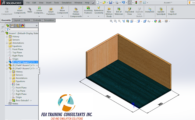
With all
three parts complete, you may apply your materials to the parts, in this case
various woods were selected.
Remember to
save your new assembly with the new parts created from the assembly. In the saving process you will encounter this
message indicating that you will need to save the parts that were created. Select save externally in order to have the
part files created.
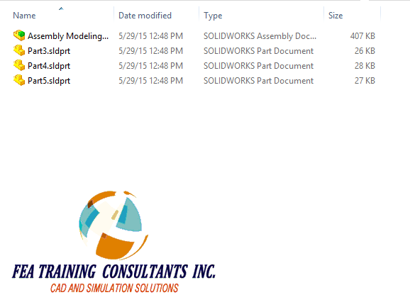
Finally, you
will find your part files created in the same file location as the assembly.


No comments:
Post a Comment