May 30, 2015

Modeling in Assembly

ASSEMBLY MODELING 


Conventional modeling practices allow users to create a part and combine multiple parts in an assembly.  It is worth knowing that this is not the only approach to modeling. You have the option to model straight from assembly mode.

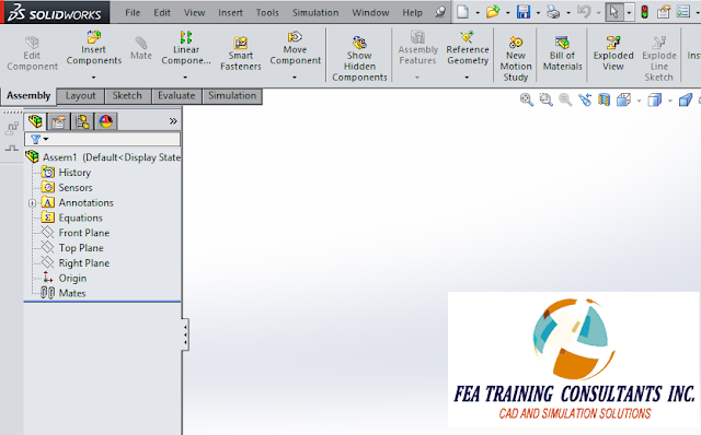
Consider a new assembly:

solidworks assembly


From this new assembly select Insert > Component > New Part.  A new generic part file will be created in the feature manager design tree:

solidworks part in an assembly


Select your part, right click and select “Edit Part”


edit part in solidworks assembly


In this example let’s sketch a simple rectangle on the top plane

sketching part in solidworrks assembly


Extrude the rectangle to create a solid.  Please note that we are still in Assembly mode, However, we are working under the “Edit Component” feature.

modeling in assembly solidworks


Similarly we can insert a new part and sketch on a rectangle on the right plane as shown.  Please note that the collinear relation was used to define the rectangle.

solidworks assembly


Extrude to create your second part

assembly solidworks


We can repeat the process to insert a new part and sketch on the front plane as shown below to make the third part

solidworks modeling assembly


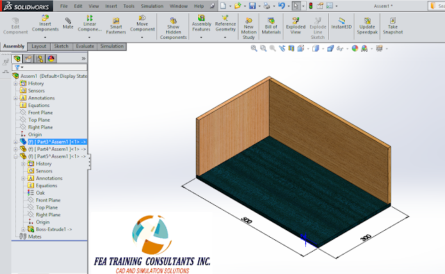
With all three parts complete, you may apply your materials to the parts, in this case various woods were selected. 

solidworks modeling


Remember to save your new assembly with the new parts created from the assembly.  In the saving process you will encounter this message indicating that you will need to save the parts that were created.  Select save externally in order to have the part files created. 

solidworks assembly


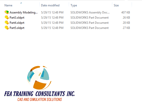
Finally, you will find your part files created in the same file location as the assembly.

solidworks assembly


May 26, 2015

Rigid and Flexible Assemblies

When creating parts in your design you will most likely create assemblies as well.  An assembly is a group of parts held together by mates.  Consider the assembly mechanism below.  The mates are created such that the top handle is able to rotate, thus transmitting the motion from one yoke to another. 


rigid and flexible assembly solidworks


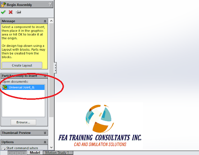
We may create subassemblies by placing one premade assembly into another.  In this case we are placing the universal joint mechanism as shown above into a new assembly

solidworks assembly


Once the universal joint mechanism assembly is placed into a new assembly, you will find that the entire mechanism is rigid and unable to move despite having no restriction for movement.


assembly mechanism solidworks


By default, when an assembly is placed into another assembly it is treated as rigid.  To change this we can right click the subassembly and select Properties


rigid assembly solidworks


When the component properties box opens navigate to the Solve as section and select Flexible.  Accept.


flexible assembly solidworks


With that change implemented you will find that the subassembly mechanism is now freely available to rotate.


May 22, 2015

Smart Fasteners (ToolBox add-in)

Using Smart Fasteners

Large assemblies are typically composed of many different parts.  Those parts are held together by many means such as interference fit or welding but a common method is to use fasteners.  Fasteners include items such as nuts, bolts and washers.  They are hardware and can be tedious to mate in large assemblies.  To alleviate the burden of individually applying fasteners, SolidWorks has a SmartFasteners tool for users to help eliminate repetitive tasks.

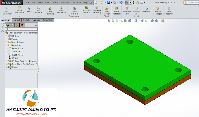
Consider two plates one stacked on top of the other with four holes that are aligned. 

solidworks add-in


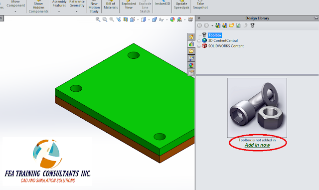
Before we use Smart Fasteners, please ensure your toolbox is added in. (Toolbox add-in can be found in SolidWorks Professional and SolidWorks Premium versions of SolidWorks)

ToolBox -add in solidworks


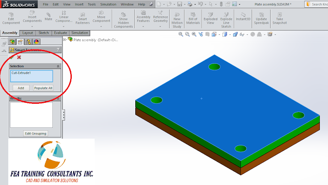
With the toolbox added in, we can select Assembly > Smart Fasteners.  Once Smart Fasteners is selected, you can pick the face with the holes as shown:

smart fasteners - tool box add -in solidworks


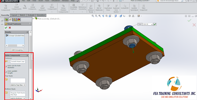
Click “populate all” and you should see fasteners populating the holes and auto size to fit the holes.  You have the option to accept the auto-sized fasteners or you can manually define it.  Furthermore you have the option to customize the stack composition as well as order.  I have chosen to add a washer and a hex nut at the bottom. 

smart fasteners toolbox solidworks


Once you are satisfied with your fasteners you may accept and a new folder will appear in the feature manager design tree representing the new fasteners series.

smart fasteners toolbox


Smart Fasteners should help you save time by populating many holes with fasteners of your choice in a short period of time.

May 20, 2015

Difference between Direct Transfer and Rigid Connection

In SolidWorks Simulation you may define external loads known as remote loads.  Upon creation of a remote load you have the option of setting it to be either Direct Transfer or Rigid ConnectionWhat is the difference?

Consider a simply supported cantilever composed of two parts: front and back: 

solidworks simulation


We may create a simulation study that reflects the cantilever beam loading conditions.  It is fixed on one end and has a load applied on the other end.

simulation study in solidworks simulation


We can simulate the results of this study by excluding half of the beam and applying a remote load in place.  

load conditions in solidworks simulation


When creating a remote load, the user must specify whether it is a direct transfer or rigid connection

direct transfer vs rigid connection in solidworks simulation


Direct Transfer: Assumes that the component between the remote force and the connection point is adequately flexible, allowing the structure to deflect.  The program decomposes the remote force into a shear force and coupling moment acting on the connection face.  This allows the connection face to distort.  Displacements must be within the small displacement assumption.

remote force - solidworks simulation


Rigid Connection:   Applies rigid links/ connections from the remote load to the connecting face.  As a result when the face deflects, the face shape is maintained.  High stresses can develop near faces with rigid connections.


rigid coneections- solidworks simulation


The results of the remote load direct transfer is shown below:

remote load direct transfer


The results of the remote load rigid connection are shown below:

rigid connection-solidworks simulation


At first glance the results are not easily distinguishable; however upon closer inspection along the vertical axis of the connection face reveals that the stress distribution from the direct transfer and rigid connection options are different.

direct transfer-solidworks simulation


rigid connection-solidworks simulation


Choosing whether the remote load will be applied as a direct transfer or rigid connection will affect the simulation results.


May 5, 2015

SOLIDWORKS 2015 SALE!

BUY SOLIDWORKS AND GET AN ADDITIONAL 

SOLIDWORKS ADD-ON LICENSE AT NO COST


From now through May 31, 2015 extend your design capabilities by including one additional SOLIDWORKS product license at no cost*.
SOLIDWORKS has a solution for every stage of your design process, allowing you to be more productive and efficient. 
This special offer makes purchasing a SOLIDWORKS Professional or SOLIDWORKS Premium license an even smarter buying decision.  Select the best add on product for your designing needs.  

For each new SOLIDWORKS Professional license purchased – add one of the following licenses:
  • SOLIDWORKS Enterprise PDM CAD Editor – manage and share product data more effectively and automate workflow to allow better collaboration between all departments
  • SOLIDWORKS Model Based Definition – offers an integrated drawing–less manufacturing solution
  • SOLIDWORKS Inspection – streamlines the inspection documentation process
For each new SOLIDWORKS Premium license purchased – add one of the following licenses:
  • SOLIDWORKS Composer – leverage 3D CAD data to create dynamic graphical content
  • SOLIDWORKS Plastics Standard – easy to use, injection molded simulation
  • SOLIDWORKS Electrical 2D or 3D– simplifies development of embedded electrical systems for products
GET STARTED TODAY!


*Offer valid from May 1 - 31, 2015 in the U.S. Canada and Mexico only. Offer expires May 31, 2015 at 11:59pm Eastern Daylight Time and cannot be combined with any other discount or offer. Only newly acquired licenses ordered after 12:00 am Eastern Daylight Time on May 1, 2015 are eligible. Educational and Research licenses do not qualify for this offer. Subscription Service must be purchased for one-year at full price on each new SOLIDWORKS Professional or SOLIDWORKS Premium license as well as full one-year subscription price on additional no cost product license(s) outlined in this offer. Other restrictions may apply. Contact FEA Training Consultants Inc. for more information.