September 30, 2014

SolidWorks Simulation:Meshing of failed Parts

If you have part(s) that fail to mesh in an assembly model, the part icon in the Simulation Parts list will be indicated by a red hashed icon, as shown in the image below.  But with the latest releases of SOLIDWORKS Simulation (2011 and above), you can fix this issue by right-clicking the part and choosing to Create Mesh for that part alone. 


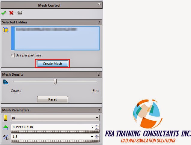
This selection will take you into the Mesh Control dialog, see image below, where you can adjust settings for the mesh size if you want, but simply clicking the Create Mesh button here will re-mesh only that part but still in the context of the assembly.


You are reminded of this fact by a pop-up telling you what is happening, see image below.  (1) It creates a mesh control in the tree, and regardless of the mesher previously used, it will mesh the failed part using the Curvature based mesher. 
(2) It will also automatically create Contact Sets using faces that are touching neighboring parts.  Most likely the reason why the part failed to mesh in the first place was that the differences in part sizes prevented it from maintaining a compatible mesh.  If there was interference between parts, another reason for parts failing to mesh, then you need to manually define the Contact Set to appropriately define their interaction


When all parts have successfully meshed, the top level Part icon will have a check indicating that everything is meshed, see image below.


September 23, 2014

How to create Macros in SolidWorks Electrical?

Do you have an electrical drawing to use in various projects?Do you have to re-create an electrical drawing in your various projects? 
SolidWorks Electrical has a time saving functionality called "Macros". With macros you can re-use your existing electrical drawing across your various projects.
Let's take a detailed look at creating macros in SolidWorks Electrical.

Creating Macros in SolidWorks Electrical

To create a Macro, open the drawing which contains the elements you want to store in the library. In the side panel activate the Macros Tab. In the graphics zone, select the entities which you want to save and Drag and drop them into one of the sections of the palette. In this case we would create a macro and drop it under Motor Command.


 Once you drag and drop to create macro a dialogue box opens allowing you to fill in the data relating to the macro. As shown below we input the value for description.


This macro is automatically added to the macros library and will thus be available for insertion into other projects.

 In the side panel, when you right click, a pull-down menu allows you to have access to the macro palettes parameters.
Add macros: Lets you select a macro stored in the library and add it to the list of macros in the palettes.
Edit this macro: Opens the macro in the graphical interface for modification. The macro is viewed as a project. It appears in the “Documents” tab in the side panel.
Delete this macro: Delete’s the selected macro from the palette (it is not deleted from the library).
New group: Creates a new macro group.
Group properties: Accesses the selected group’s properties.
Delete group: Deletes the selected group
Activate group: Activates the group with is selected from the contextual menu.


Macros are grouped together within the Macros manager and are thus available for use by all projects. The macros have filtering criteria allowing classification. It can be accessed from Library > Macros manager as shown below.


Inserting Macro

Open the drawing in which you want to insert the macro and "Drag and Drop" the macro from the side panel into the graphic zone. When the macro is inserted, the marks management dialog box opens, allowing you to either calculate new marks or keep the existing marks.


As shown below the marks have been incremented with the inclusion of manufacturer part information. There is also new cross reference table added for new contactor coil. Since its power contacts are not yet used, they are displayed blue in the table.


September 5, 2014

SolidWorks 2015 Launch & Training Seminar - Oct 3, 2014

It is that time of the year again and  We’re excited to present SOLIDWORKS® 2015, offering new tools and solutions to boost your engineering and design productivity. With new features like simplified geometry creation, faster simulation analysis, enhanced cost analysis, and improved integration with downstream processes, SOLIDWORKS 2015 will enable you to jump-start your creativity and Inspire Innovation. Be part of the excitement. Register for the SolidWorks 2015 Training Session and explore SolidWorks 2015 product solutions.


Proud Co-Sponsor for the SolidWorks 2015 Launch & Training Seminar - HP|Intel