SolidWorks Drawings: Alternate Position View
For 2D mediums such as drawings it may be
difficult to present range of motion for moving parts in mechanical
assemblies. A solidworks tool that comes
in very handy for such problems is the Alternate Position View in drawings. Alternate position allows you to superimpose
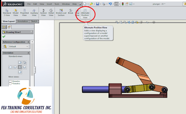
one position over another to demonstrate range of motion of an assembly. Consider the following mechanism:
It is a
simple mechanical mechanism with a specific range of motion. When a drawing is created for this mechanism
we want to select view layout > Alternate Position View.
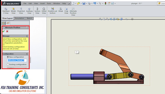
This will
allow you to create a new configuration with the new position. You may rename the configuration as required
and select the green check to proceed.
The
software will now open the model with a move component free drag selected. From here you may click and drag any face on
the component to rearrange it to the new position
When you are
satisfied with the new position, click the check mark to accept it and you
should find on the drawing the alternative position superimposed onto the
original configuration. The alternative
position will be transparent as to distinguish the two.


No comments:
Post a Comment