Simulation: Application of Loads
SolidWorks Simulation allows users to set up
and run tests using finite element analysis (FEA).
The manner in which a user sets up a test will determine whether the
results are an accurate result of real-world conditions. (Also Read:Symmetry in SolidWorks Simulation -Guide to applying loads and restraints appropriately)
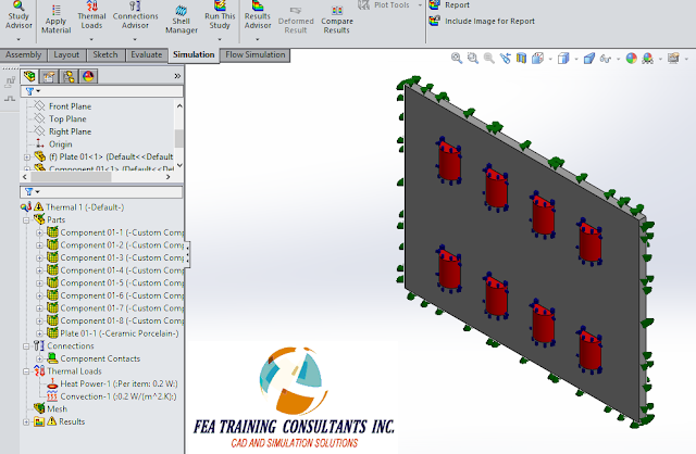
Consider
the electrical component shown below.
The main grey surface consists of ceramic porcelain whereas the small
red parts indicate components that generate heat on the board. We are interested in the heat distribution
for this part under working conditions.

In order to
set up the problem we define the material properties for each component. This includes the red electrical components
as well as the grey ceramic porcelain.
Following material definition, we define heat generation power of 0.2W
for the red components and convection of 0.2 W/m^2 K for the outside
surfaces. The convection is a mechanism
of heat transfer used to dissipate the heat.
It is
important to pay attention to detail when defining a simulation study. Consider the definition of 0.2W heat
generation for the red components. The
user must differentiate whether the heat generation is generated for each
component or whether it is generated across the sum total of components. This is an important distinguishing
factor. In this case it is set to “Per
item” which is correct.
Furthermore,
as a tip, if the user were to use symmetry to divide a heat generating part in
half and the heat generation is defined in terms of Watts, it follows that the
Watt value must also be divided by half since Watt is a total heat generating
value. The relationship is similar to
that of force and pressure.

Once the
analysis is successfully set up we need to mesh the component.

Once the
component is meshed, we may run the analysis.
According to the conditions set for this thermal analysis we are seeing
a maximum value of 460C occurring on the inner components. The heat generated from the components
travels outward to a temperature of 427C towards the outer edges of the ceramic
porcelain.

The manner
in which the simulation analysis was set up can greatly affect the
results.


No comments:
Post a Comment