December 13, 2015

SolidWorks 2016:Splines and Surfaces

New functionality to splines and surfaces in SOLIDWORKS 2016


 Consumer Products can be challenging to model with complex surfaces and the use of sketched splines.  SolidWorks 2016 adds new functionality to splines and surfaces to make modeling consumer products faster and easier.

Consider the following Jug:

SPLINES AND SURFACES

This is an image of a jug and we would like to create a 3D model based on this image.  We start by first sketching the neck side profile of the jug:

style spline

New to SOLIDWORKS 2016 is the ability to choose between B-Splines as well as Bezier curve types.  Using B-Splines, we click to place our control points:

spline and surfaces new features solidworks 2016


Following the control points, it is a good idea to turn on the “Show Curvature” option that allows the designer to visualize the curve.  

spline curvature

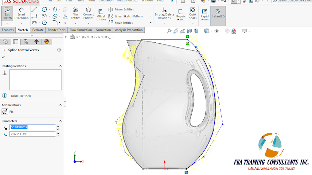
With this in mind the designer may now click and dynamically drag the control points so they fit the form of the jug.  Now the curvature of the handle portion was approximated with a spline. 

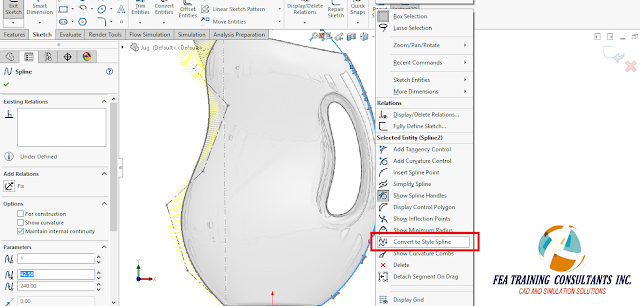
convert to spline 

The designer may now select the spline and select the convert to style spline from the fly out menu.

spline and surfaces  

In doing so, we have a one to one conversion since the resulting style spline will be a B-Spline with degree 3.  The designer may how adjust the control points to modify the curve to match the side handle profile.  With style splines it’s easier to create curves that are fast and easy to manipulate.
Having created the main surface and a few more control surfaces, the designer needs to trim all the surfaces to get the consumer product shape.

spline and surfaces solidworks 2016

In SolidWorks 2016, SolidWorks Trim Surface is easier to use with new preview tools.  By selecting “show excluded regions” the software shows the surfaces that will be excluded from the trim.  

surfaces solidworks 2016

Furthermore, the preview option for Trim Surface can also be switched to show only the surfaces left after applying the trimming feature.  If the Trimming feature yields a solid body, a new “Create Solid” option is now available to allow users to create a solid directly from the trim without any additional operation.

Following the main trim, the designer can now apply smooth asymmetrical fillets on the base:

surfaces solidworks2016


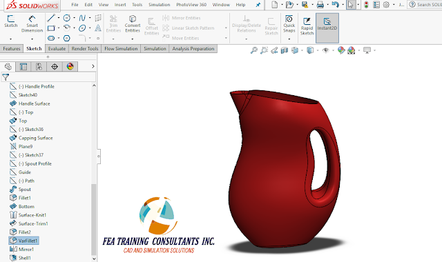
And complex variable fillets on the handle with control points:

solidworks 2016 splines and surfaces

Followed by a mirror function and shell operation to get the final jug product:

splines and surfaces

The additional functionalities to splines and surfaces in SolidWorks 2016 are meant to make modeling consumer products with complex shapes easier and quicker.


December 10, 2015

Sketching Improvements in SOLIDWORKS 2016

IMPROVEMENTS IN SOLIDWORKS SKETCHING 2016

 Sketching is perhaps one of the core functionalities in the SolidWorks software.  Sketches allow a user to create 2 dimensional entities that may be used to create complex features.  It is a tool that helps the designer shape the part into the correct geometry.  With SolidWorks 2016 there have been improvements to the sketching abilities to make modeling easier.

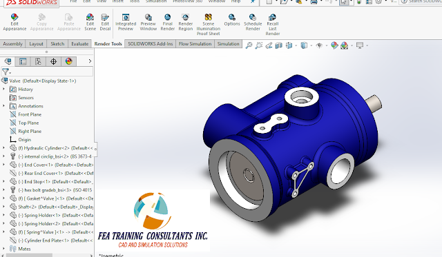
Consider the following Valve

sketching solidworks


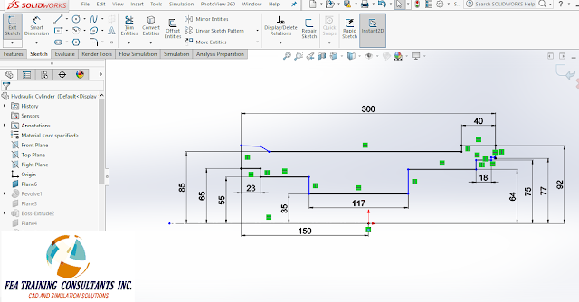
By opening up the base sketch used in the revolve feature to create the valve body we have the following sketch:


sketch solidworks

HIDE SKETCH DIMENSIONS:

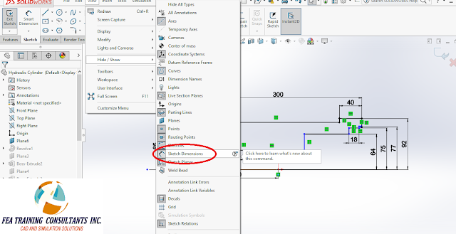
Sketches become more complex with the addition of geometrical features.  There may be times when the dimensions constraining the sketch become cluttered to view in the graphical area.  In SolidWorks 2016 there is a new tool to hide sketch dimensions.  This is found under Tools> Hide/Show/ Hide Sketch Dimensions. By applying this filter to the graphical viewing area, it makes it much easier for the designer to inspect the current state of the sketch.

hide/show/hide sketch dimensions

sketching in solidworks 2016


MIDPOINTS:

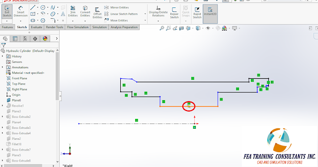
When a designer is dimension or adding relations to a sketch, the midpoint is a useful entity to have available.  Midpoints are now automatically selectable without explicitly defining a midpoint entity.  This change helps expedite the sketching process allowing designers to fully define a sketch in fewer steps than before.

sketching midpoint


SMART DIMENSION:


In addition, it is no longer necessary to select the smart dimension icon before clicking on the entities that require dimension.  Instead, designers can now select the entities of interest and a fly out menu will appear beside the mouse.  Designers may now select the Smart Dimension icon from that menu and the software will provide the appropriate dimension for the entities selected.  

smart dimension solidworks sketching\


sketching impovements in solidworks 2016


INSTANT 2D:

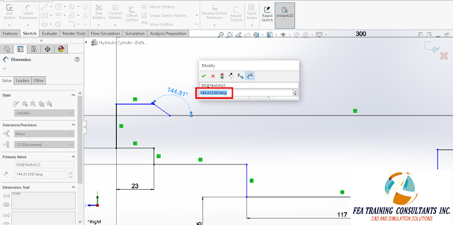
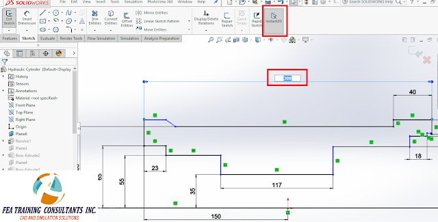
Another useful tool is Instant 2D which is a feature that allows users to modify the value of a dimension with a single click.  Instant 2D can be found on the sketch toolbar.

instant 2D solidworks sketching


December 7, 2015

Whats New in SolidWorks 2016: Photoview 360

PhotoView 360


  PhotoView 360 has been used in SolidWorks to generate life-like renderings of SolidWorks models.  These renderings are excellent communication tools to showcase your product as it would appear in real-life.  SolidWorks 2016 has added new features to PhotoView 360 to streamline the rendering process.

Consider the following stapler:

photoview 360


The preview window is a feature we can access from the Render Tools tab and it allows the designer to preview the render before it is applied to the model.  This is a valuable tool because to fully render a model takes time and a preview window helps the designer decide whether they would like to proceed or not.

solidworks photoview 360

The preview window now has a resolution slider on the bottom that increases or decreases the quality of the preview render.  This gives the designer more control over the quality of render being previewed.  The designer can dynamically change this value depending on whether it is approaching the desired render effect. 

photoview 360 solidworks 


The edit scene feature is also available from the Render Tools Tab and it allows the designer to edit the lighting, reflectivity and environment variables that effect the final render.  This has usually been an iterative process requiring multiple trials before arriving at the desired image render.  A new tool to help with this process is the Scene Illumination Proof Sheet feature from the Render Tools Tab.

solidworks photoview


The Scene Illumination Proof Sheet feature uses the base render as baseline and shows multiple previews of multiple variations. This includes rendering brightness, background brightness and scene reflectivity.  

solidworks photoview 360

Each of these tiles displays a preview of the rendered image with modifications.  By selecting a tile, it replaces the baseline render and recalculates all of the previews based on the new baseline.  This functionality allows the designer to home-in on the desired rendering faster and more efficiently.  At any point in time, the designer may flip between the original and current baseline for comparison using the tabs provided.  By selecting OK, the settings will be applied to the PhotoView 360 scene allowing the designer to start rendering the final product.  

The improved functionality in PhotoView 360 allows designers to converge on the desired rendered look faster and more efficiently in SolidWorks 2016.