January 28, 2013

SolidWorks World Day 3 General Session Video

SolidWorks World 2013 wounded up in Orlando, Florida. Here is the video of the General Session on Day 3 at SolidWorks World. The Video includes:

  • Presentation by SolidWorks Partner Dell
  • 2013 Model Mania Contest Winners
  • SolidWorks in Student Community
  • Presentation by Tom Atchison, CEO, Chariman and Founder of Rocket Mavericks working with students to design and build rockets.
  • NVIDIA Presentation
  • Top 10 popular enhancements
  • Thank you address by SolidWorks CEO Bertrand Sicot.


January 24, 2013

Mass Properties Dialog Box,Center of Mass (COM)


The Mass Properties dialog box has been enhanced to improve workflow and clarify options.

Some of the changes include:

• The Assigned mass properties option has been replaced by the Override Mass Properties button. When you click Override Mass Properties, the new Override Mass Properties dialog box appears. As in previous releases, you can override values for mass and center of mass. Now you can also override moments of inertia.

• For assemblies, if one or more components has mass properties that have been overridden, the components are listed at the bottom of the Mass Properties dialog box.

Output coordinate system has been changed to Report coordinate values relative to. The contents of the drop-down list remain the same.

• The Print and Copy buttons have been moved to the bottom of the dialog box, and a Help button has been added.

Show output coordinate system in corner of window has been moved to the Mass/Section Property Options dialog box. Click Options in the Mass Properties dialog box.


solidworks mass properties dialog box
 
 
Point at the Center of Mass
 
You can add a Center of Mass (COM) point to parts, assemblies, and drawings. You add a COM by clicking Center of Mass (Reference Geometry toolbar) or Insert > Reference Geometry > Center of Mass.


In the graphics area, appears at the center of mass of the model. In the Feature Manager design tree, Center of Mass appears just below Origin


The position of the COM point updates when the model’s center of mass changes. For example, the position of the COM point updates as you add, move, and delete features in a part.
The COM point can be suppressed and unsuppressed for configurations. You can measure distances and add reference dimensions between the COM point and entities such as vertices, edges, and faces.
You cannot create driving dimensions from the COM point. However, you can create a Center of Mass Reference Point (COMRP), and use that point to define driving dimensions.
A COMRP is a reference point created at the current center of mass of the part. It remains at the coordinates where you create it even if the COM point moves due to changes in the geometry of the part.
To create a COM reference point:
• Right-click the Center of Mass in the Feature Manager design tree and click Center of Mass Reference Point


January 23, 2013

SolidWorks World 2013 - Day 2 General Session VIDEO

The second day of SolidWorks World was exciting as always, with presentations from Dr. Vijay Kumar (Professor, School of Engineering & Applied Sciences, University of Pensylvania) and Festo talking about the future of robotics research. See all the action in this video.

January 22, 2013

SolidWorks World 2013 - Day 1 (General Session) VIDEO

SolidWorks World 2013 is presently in progress at Walt Disney World Swan and Dolphin Orlando, Florida, USA. Watch the video below to see what happened on Day 1 and the video includes:
 
  • Key Note address by SolidWorks CEO Bertrand Sicot
  • Announcement of MY SOLIDWORKS a new way to experience Solidworks Community.
  • Announcement of SolidWorks Mechanical Conceptual a new platform in Dassault Systemes 3D Experience
  • A presentation from the Red Bull Stratos Engineering team on their journey of breaking the skydiving world record from the edge of space


January 21, 2013

Dowel Holes in Holes Wizard


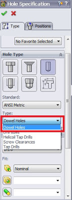
You can insert standard dowel holes using the Hole Wizard. Dowel holes are used to align components in assemblies. You can choose from standard diameters, or assign custom diameters appropriate to your industry.

To insert the dowel hole: 

1. Click Hole Wizard (Features toolbar).

2. In the Type tab of the Property Manager:

a) Under Hole Type, click Hole.

b) In Type, select Dowels.

c) Set the remaining options as needed.

3. Click OK.


hole specification tool in solidworks


Dowel Pin Symbol Support
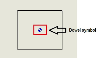
There is a new document option for the automatic creation of all dowel pin symbols on view creation as shown below. Additionally, you can automatically insert all dowel pin symbols in a drawing view after view creation.
 
 
dowel pin symbol support
 
 
Automatically Inserting Dowel Pin Symbols
To automatically insert dowel symbols after view creation:
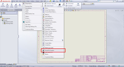
1. In a drawing, click Dowel Pin Symbol (Annotation toolbar) or right-click and click Annotations > Dowel Pin Symbol.
2. In the Dowel Pin Symbol Property Manager, under Auto Insert, select For all dowel holes.
3. Set the options.
4. Select one or more drawings views.
5. Click to insert the dowel pin symbols.


solidworks 2013 autmatic inserting of dowel pin


Setting Document Properties for Dowel Pin Symbols

To set the document properties to automatically create all dowel pin symbols on view creation:

1. In a drawing, click Tools > Options.

2. On the Document Properties tab, click Detailing.

3. Under Auto insert on view creation, select:

Dowel symbols -part

Dowel symbols -assembly

4. Click OK.


January 14, 2013

Solve Heat Transfer problems Quickly and Cost-Effectively with Flow Simulation

Finding effective solutions to heat transfer problems has become an increasingly important part of new product development. Almost everything experiences heating or cooling of some kind, and for many products, such as modern electronics, medical devices, and HVAC systems, managing heat is a critical requirement for avoiding overheating and achieving functional success. Manufacturers who can efficiently resolve heat transfer issues will have a distinct competitive advantage. With an easy-to-use, fluid-flow analysis application like SolidWorks Flow Simulation software, you will have the tools that you need to solve even the most difficult heat transfer problems, while saving time and money in the process.  

DOWNLOAD WHITEPAPER

solidworks flow simulation - heat transfer
 

January 11, 2013

Measure Tool in SolidWorks 2013


Improvements have been made to the Measure Tool functionality and user interface.


Point-to-Point Mode

You can measure the distance between two points on your model. This mode supports snapping to model faces and edges, as well as midpoints, quadrant points, and intersections.


Arc/Circle Measurements

You can create measurements with custom arc conditions. For example, you can measure

the distance from the center of one arc or circle to the outer edge of another. Use drop-down menus on the Measure callouts in the graphics area to toggle between center, maximum, minimum, and custom distances.


Last Used Settings

The Measure tool retains settings from the last time it was used.

History

Click History to see measurements made during the current session of SolidWorks.


User Interface

The Save icon has been replaced with Sensor to indicate the option to create a sensor from the current measurement.


January 9, 2013

SolidWorks Essentials Weekend Training Course

Looking to learn SolidWorks in a slow paced environment? Don't have time to attend a course on Weekday? Then, this weekend training option is ideal for you.

FEA Training Consultants Inc. is an Authorized Training and Support Center . We offer hands-on training courses taught by award winning certified SolidWorks Instructors. At FEA Training Consultants Inc. we are committed to teaching the skills SolidWorks is designed to deliver.

FEA Training Consultants Inc.’s training program focuses on unique training needs of each customer.
Locations: Our Authorized Training and Support Center are complemented with state-of-the-art training labs that allow us to offer hands-on training in our office, or on-site at your facility.
Managable Class Size:
FEA-TC is committed in keeping a small class size to enable personalized attention.
Certified Instructors: All our training classes are taught by Certified SolidWorks Instructors with heavy practical knowledge

WEEKEND SOLIDWORKS ESSENTIALS COURSE DETAILS

COURSE STARTS FEBRUARY 02, 2013 (FOR 4 WEEKS)
COURSE TIME : 9AM-1PM

GET STARTED TODAY!