Curve through xyz points
Data can be
provided to the designer in a variety of ways from contract drawings, field
measurement, word of mouth etc. In the
case of field measurement or established geometries, the data can come in the
form of a plotted coordinate system.
Let us
consider the profile of an airfoil. The
geometrical features of an airfoil effect the flow and thus performance of the
airfoil in operation. It is important to
model the geometry as accurately as possible.
The geometry is given in the form of an x-y coordinate system.
It is worth
noting that an additional column was added with all zeros in order to represent
the dimensions for the Z plane. The
three column as given in excel format is not as useful, therefore we can copy
the data by selecting the columns and selecting copy and paste it in a text document.
Save the
text document since you will need to select it soon.
Next we can start a new part in
SolidWorks. In order to bring the
airfoil into SolidWorks you can sketch individual points and draw a spline
connecting all the points. This manual
method is repetitive, labor intensive and time consuming. A more efficient method would be to use the
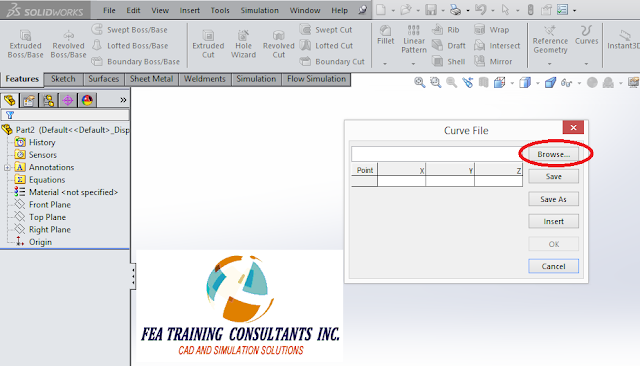
“Curve through XYZ Points” tool from the feature tab.
After
selecting “Curve through XYZ Points”, click on browse and select the text file
with the coordinates that was created.
Upon selection you should see the points and
data values populating the X, Y and Z coordinates. Select “OK”.
Now you should have a full accurate curved
geometry that was constrained by the X,Y and Z coordinates that were
imported. Creating this curve using this
method is significantly quicker than manually plotting each point and
connecting them with a spline. “Curve
through XYZ Points” is one of many features that makes solid modeling faster
and more efficient in SolidWorks.


No comments:
Post a Comment